03217917-01-01E By DEK Technical Reference Manual Vol 1_enPDFA.pdf - 第242页
16 TRANSPORT RAILS MODULE 16.4 ADJUSTMENTS AND SETTINGS 242 TECHNICAL REFERENCE MANUAL Vol 1 E By DEK 04/2019 16.4.4 Foil-less Clamp Height Adjustment Foil-Less Clamps are height adjustable to accommodate for different b…
16 TRANSPORT RAILS MODULE
16.4 ADJUSTMENTS AND SETTINGS
TECHNICAL REFERENCE MANUAL Vol 1 E By DEK 04/2019 241
1
2
2
250mm Board Clamp Mechanism
► Adjust the board clamp to achieve the setting of 0.325mm +/-0.025mm between the rear
board clamp and the belt support plate.
► 500mm Board Clamps Only. When the correct setting has been achieved tighten the location
plate securing screws through the access holes in the board clamp, with a small bladed
screwdriver.
► 250mm Board Clamps Only. When the correct setting has been achieved tighten the location
plate securing screws through the access slots.
► Recheck that the gap between the rear board clamp and the belt support plate is 0.325mm
+/-0.025mm.
Front Board Clamp Gap Adjustment
► Repeat Rear Board Clamp Gap Adjustment procedure for the front board clamp.
Board Clamp Parallelism Check
► Using a vernier gauge check that the board clamps are parallel, to within 0.1mm, at the left,
centre and right of the board clamps.
► If adjustment is necessary, slacken the location plate securing screws on the rear rail and ad-
just. Tighten the location plate securing screws on completion.
► If any adjustment is carried out, ensure the board clamp gap set previously is maintained.
► 500mm Board Clamps Only. Lift off the rear rail board clamp and further tighten the location
plate securing screws, with a larger bladed screwdriver.
► 500mm Board Clamps Only. Place the rear rail board clamp in position and secure with the
four securing screws.
► 500mm Board Clamps Only. Repeat last two steps for the front rail.
► Refit the belt guide to either side of the rear rail belt support plate.
► Refit the belt guide to either side of the front rail belt support plate.
► Ensure correct operation of the board clamps after any adjustment is made.
16 TRANSPORT RAILS MODULE
16.4 ADJUSTMENTS AND SETTINGS
242 TECHNICAL REFERENCE MANUAL Vol 1 E By DEK 04/2019
16.4.4 Foil-less Clamp Height Adjustment
Foil-Less Clamps are height adjustable to accommodate for different board thickness. Adjust the
clamp height for the product to be printed.
► Select Open Cover Commands.
► Select Carriage To Rear.
► Select Unload Screen.
► Open the printhead cover.
► Remove the stencil from the machine.
► Place a product board centrally between the foil-less clamps.
► Close the printhead cover.
► Press the System button.
► Select Maintenance.
► Select Diagnostics.
► From the displayed table, using the Next or Previous button highlight RailSystem.
► Select Select Module.
► Using the Next or Previous button highlight Toggle Board Clamp.
► Select Run Diagnost.
► Open the printhead cover.
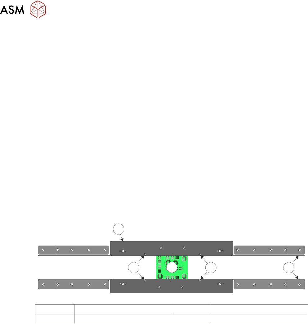
► Adjust the two downstop screws on each clamp such that the top of the board and clamp are
flush aligned.
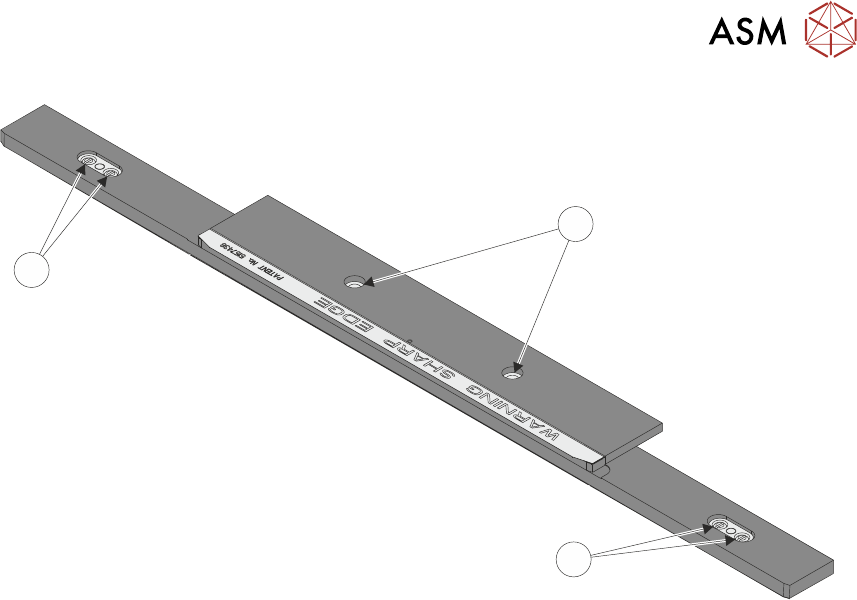
4
2
3
2 1
1 Transport Belts 3 Board
2 Downstop Screws 4 Rear Foil-less Clamp
► Close the printhead cover.
► Press the System button.
► Select Run Diagnost. Check that the board is held without coming out of the rails.
► Select Adjust.
► Using the Next or Previous button highlight Cycle Count.
► Using the Incr. or Decr. button change the cycle count to 10.
► Select Exit.
► Using the Next or Previous button highlight Cycle Board Clamp.
► Select Run Diagnost. Ensure that the clamps open and close without disturbing the board.
► Ensure that once the cycle has finished the board clamps are Off. If not, using the Next or
Previous button highlight Toggle Board Clamp.
► Select Run Diagnost.
► Open the printhead cover.
► Refit the stencil.
► Remove the product board.

16 TRANSPORT RAILS MODULE
16.4 ADJUSTMENTS AND SETTINGS
TECHNICAL REFERENCE MANUAL Vol 1 E By DEK 04/2019 243
► Close the printhead cover.
► Press the System button.
► Select Exit.
► Select Exit.
► Select Back.
16.4.5 Front Rail Parallelism
WARNING
BOARD CLAMPS. EXTREME CARE MUST BE EXERCISED WHEN WORKING IN
THE TOOLING AREA OF THE MACHINE TO AVOID INJURY. THE FOILS ON THE
FRONT AND REAR BOARD CLAMPS ARE VERY SHARP.
NOTE
The Front Rail Parallelism is factory set and shouldn’t normally need to be adjusted.
Parallelism Setup
► Select Open Cover Commands.
► Select Carriage To Rear.
► Select Unload Screen.
► Open the printhead cover.
► Remove the stencil from the printer.
► Close the printhead cover.
► Press the System button.
► Select Back.
► Select Maintenance.
► Select Diagnostics.
► Using the Next or Previous button highlight Rail System.
► Select Select Module.
► Ensure that Home Rail Width is highlighted.
► Select Run Diagnost.
► Select Exit.
► Using the Next or Previous button highlight Rising Table.
► Select Select Module.
► Use Next or Previous to highlight Raise Table to Vision Height.
► Select Run Diagnost.
► Select Exit.
► Using the Next or Previous button highlight Rail System.
► Select Select Module. The board clamps are released.
► Open the printhead cover.
► Remove any tooling from the manual tooling plate.
► Remove the board clamp from the front transport rail, Board Clamp Replacement - Replace-
ment Procedures section of this chapter refers.
► There are two versions of the rail setting jig and they are labelled:
●
Standard Rails (Part No. 199140 - round belts)
●
Heavy Board Rails (Part No. 199142 - flat belts)
► Confirm which type of rails are fitted to the machine and select the appropriate rail setting jig.