03217917-01-01E By DEK Technical Reference Manual Vol 1_enPDFA.pdf - 第245页
16 TRANSPORT RAILS MODULE 16.4 ADJUSTMENTS AND SETTINGS TECHNICAL REFERENCE MANUAL Vol 1 E By DEK 04/2019 245 Parallelism Check ► Using feeler gauges (6) check that the gap between both alignment pads (8) and the belt su…
16 TRANSPORT RAILS MODULE
16.4 ADJUSTMENTS AND SETTINGS
244 TECHNICAL REFERENCE MANUAL Vol 1 E By DEK 04/2019
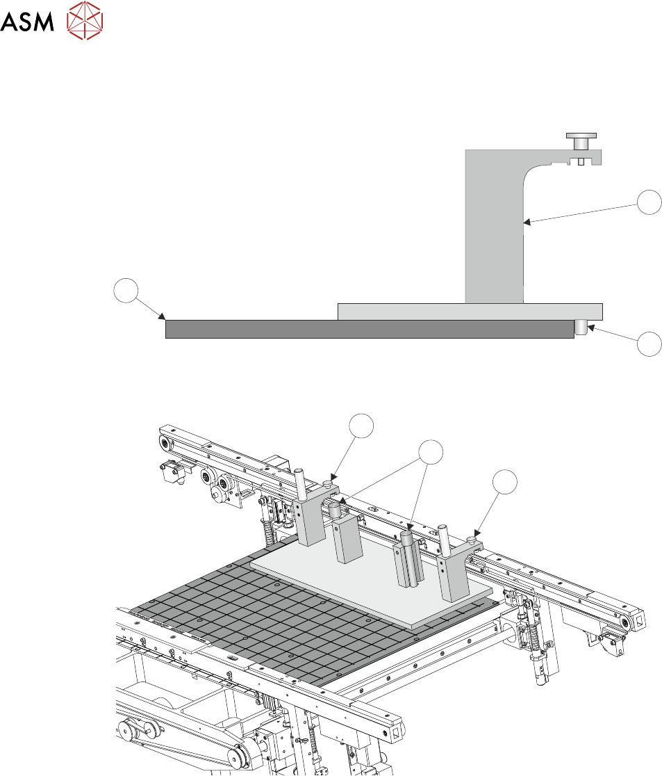
► Place the jig (1) on the manual tooling plate (3) ensuring that the location pins (2) on the un-
derside of the jig (1) abut the front face of the manual tooling plate (3). Check there is no gap
using a 0.05mm feeler gauge.
3
1
2
► Secure the jig (1) to the front rail using the two jig to rail thumbscrews (4).
4
5
4
► Secure the jig (1) to the rising table using the two jig to table thumbscrews (5).
► Check that the location pins (2) are up against the front edge of the manual tooling plate using
a 0.05mm feeler gauge and there is no gap.
16 TRANSPORT RAILS MODULE
16.4 ADJUSTMENTS AND SETTINGS
TECHNICAL REFERENCE MANUAL Vol 1 E By DEK 04/2019 245
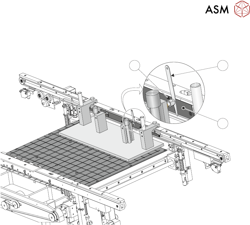
Parallelism Check
► Using feeler gauges (6) check that the gap between both alignment pads (8) and the belt sup-
port plate (7) of the front rail is 0.25mm +/-0.05mm.
8 6
7
► If adjustment is not necessary continue with Close Up.
16 TRANSPORT RAILS MODULE
16.4 ADJUSTMENTS AND SETTINGS
246 TECHNICAL REFERENCE MANUAL Vol 1 E By DEK 04/2019
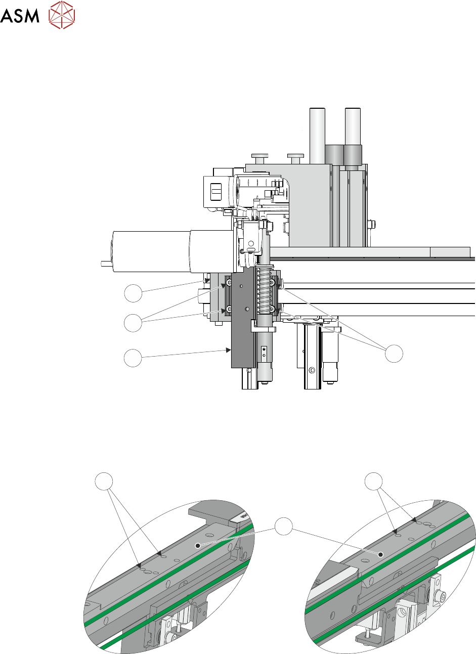
Adjustment
► Using a 3mm Allen key slacken the four securing bolts (9) attaching the right hand transport
leg (10) to the carriage nut (11).
9
10
9
11
► Repeat previous Step on the left hand transport leg.
► Using a 4mm Allen key, through the access holes (12) in the board edge guide (13), slacken
the four rail securing bolts (two each side).
RH End LH End
12
13
12
► Loosen the two jig to rail thumbscrews on the rail setting jig.
► Adjust the front rail position to achieve the settings in Parallelism Check.
► Tighten the two jig to rail thumbscrews on the rail setting jig.
► Recheck the parallelism as detailed in Parallelism Check.