03217917-01-01E By DEK Technical Reference Manual Vol 1_enPDFA.pdf - 第247页
16 TRANSPORT RAILS MODULE 16.4 ADJUSTMENTS AND SETTINGS TECHNICAL REFERENCE MANUAL Vol 1 E By DEK 04/2019 247 ► Tighten the bolts slackened at the start of this Adjustment . ► Recheck the parallelism as detailed in Paral…
16 TRANSPORT RAILS MODULE
16.4 ADJUSTMENTS AND SETTINGS
246 TECHNICAL REFERENCE MANUAL Vol 1 E By DEK 04/2019
Adjustment
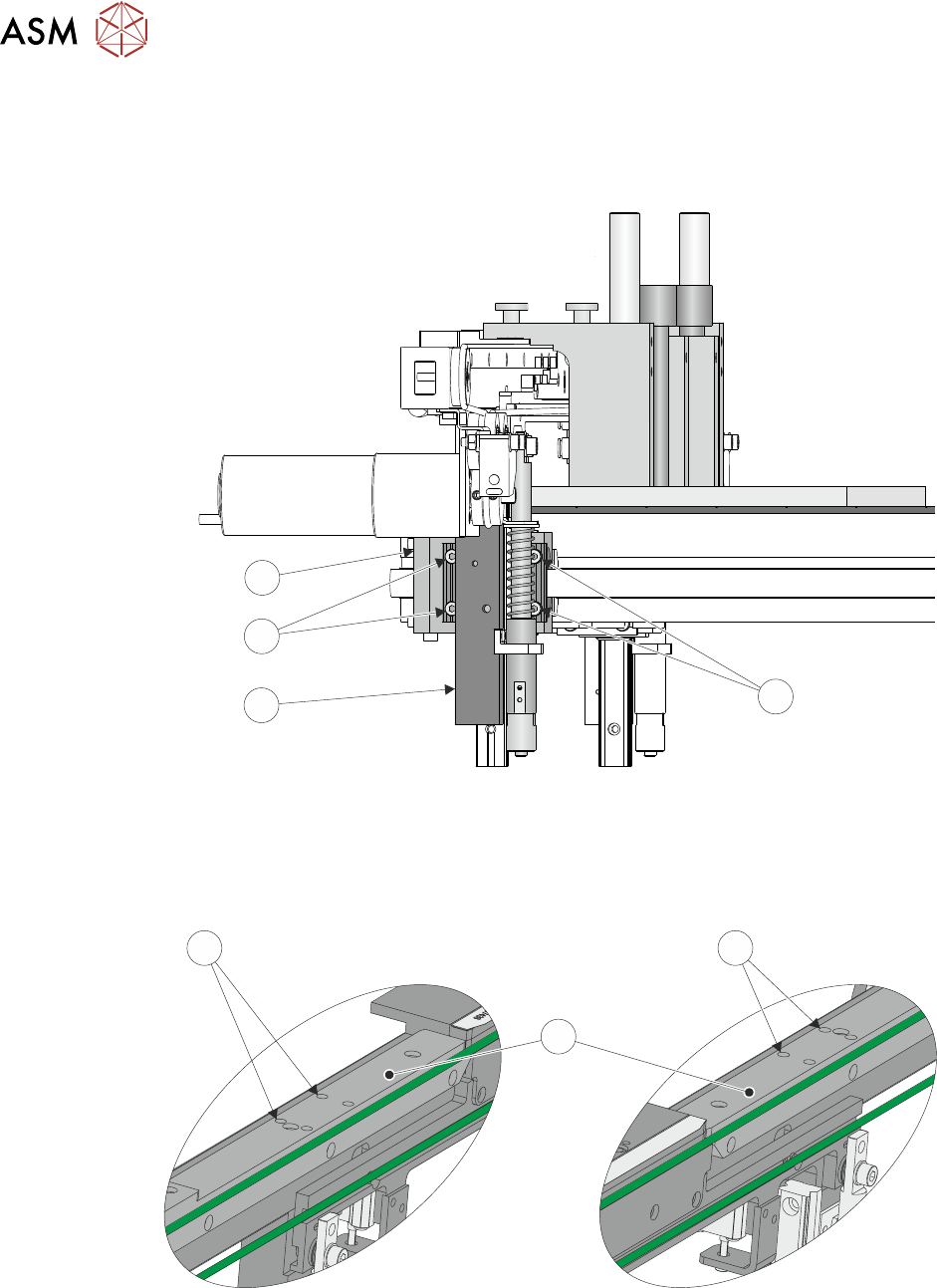
► Using a 3mm Allen key slacken the four securing bolts (9) attaching the right hand transport
leg (10) to the carriage nut (11).
9
10
9
11
► Repeat previous Step on the left hand transport leg.
► Using a 4mm Allen key, through the access holes (12) in the board edge guide (13), slacken
the four rail securing bolts (two each side).
RH End LH End
12
13
12
► Loosen the two jig to rail thumbscrews on the rail setting jig.
► Adjust the front rail position to achieve the settings in Parallelism Check.
► Tighten the two jig to rail thumbscrews on the rail setting jig.
► Recheck the parallelism as detailed in Parallelism Check.

16 TRANSPORT RAILS MODULE
16.4 ADJUSTMENTS AND SETTINGS
TECHNICAL REFERENCE MANUAL Vol 1 E By DEK 04/2019 247
► Tighten the bolts slackened at the start of this Adjustment.
► Recheck the parallelism as detailed in Parallelism Check.
► When the adjustment is complete, remove the board edge guides from each end of the rail.
► Remove each bolt disturbed (one at a time), apply a suitable locking compound and fully
tighten.
► Refit the board edge guide to each end of the rail.
Close Up
► Remove the rail setting jig from the rising table.
► Fit the board clamp to the front rail.
► Close the printhead cover.
► Press the System button.
► Select Exit.
► Select Exit.
► Select Back.
16.4.6 Rear Rail Parallelism
WARNING
BOARD CLAMPS. EXTREME CARE MUST BE EXERCISED WHEN WORKING IN
THE TOOLING AREA OF THE MACHINE TO AVOID INJURY. THE FOILS ON THE
FRONT AND REAR BOARD CLAMPS ARE VERY SHARP.
NOTE
Ensure Front Rail Parallelism has been carried out prior to commencing this procedure. It is recom-
mended the rear rail parallelism procedure is carried out by two persons.
► Select Shut Down.
► Select Continue.
► Switch the mains isolator to OFF. Use a suitable lock to lockout the electrical circuit.
► Open the printhead front cover.
► Remove the left and right machine side panels.
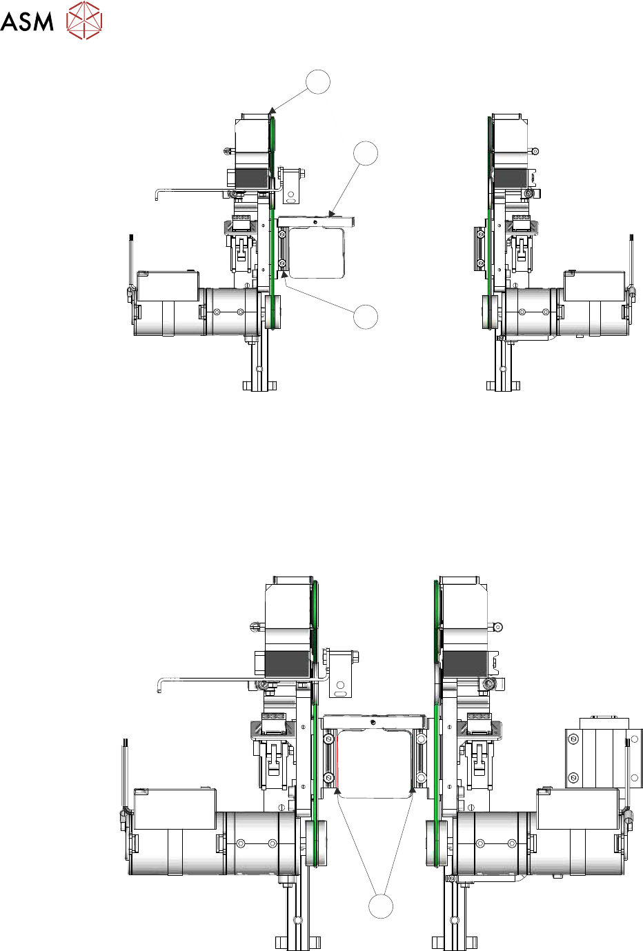
► Manually wind the rear transport rail leadscrew to move the rail forwards.
► Rest a pair of transport rail tools (2) (Part No 205530) on both left and right front transport rail
linear guide bearing blocks (3).
16 TRANSPORT RAILS MODULE
16.4 ADJUSTMENTS AND SETTINGS
248 TECHNICAL REFERENCE MANUAL Vol 1 E By DEK 04/2019
1
2
3
► Checking both left and right, continue to manually move the rear rail to close the gap for a
snug (not tight) fit.
Paralleism Check
NOTE
If the rails are not parallel, one side makes contact before the other side. Go to Adjustment to ad-
just the rails.
► Attempt to slide a 0.05mm feeler gauge between the rear bearing blocks (4) (left and right
hand side) and the transport rail tools (front and rear); as shown below:
4
► If both sets of linear guides are without gaps, the rear transport rail is parallel to the front rail,
go to Close Up.