03217917-01-01E By DEK Technical Reference Manual Vol 1_enPDFA.pdf - 第251页
16 TRANSPORT RAILS MODULE 16.4 ADJUSTMENTS AND SETTINGS TECHNICAL REFERENCE MANUAL Vol 1 E By DEK 04/2019 251 ► Select Run Diagnost . ► Select Adjust and set the board width to 250mm . ► Select Exit . ► Use Next or Previ…

16 TRANSPORT RAILS MODULE
16.4 ADJUSTMENTS AND SETTINGS
250 TECHNICAL REFERENCE MANUAL Vol 1 E By DEK 04/2019
► Close the printhead cover.
► Press the System button.
► Select Back.
► Select Maintenance.
► Select Calibrations.
► Select Classic Calibrations.
► Select Offset.
► Select Rail Width Offset. Open the rail width offset window.
► Select Incr. or Decr. to set the offset required to increase or decrease the rail width dimen-
sion.
► Place the calibration board on the input transport rail belts. Manually move the board into the
tooling area of the printer. Check for any clicks or knocks where the board may catch on the
shoulders of the rail, or mid section modules. If tight areas are detected the rails should be ad-
justed.
► With the board in the tooling area, use a 0.2mm feeler gauge between the edge of the board
and the snugger plate. If the feeler gauge is either tight or loose, adjust the ‘Set Rail Board
Width Calibration’ accordingly.
► Select Exit.
► Select Back.
► Select Diagnostics.
► Using the Next or Previous button highlight Cycle Board on Belts.
► Close the printhead cover.
► Press the System button.
► Select Maintenance.
► Select Diagnostics.
► Using the Next or Previous button highlight Cycle Board on Belts.
► Select Run Diagnost.
► Place the calibration board on the input transport rail belts.
► Select Auto Board and ensure the board runs through the entire length of the rail system for
10 complete cycles, without jamming or excessive clicking of the board edges.
► Select Stop.
► Select Exit.
16.4.8 Home Position Rail Width Check
Ensure that the board clamps are fitted and the Board Clamp Setting procedure (this section refers)
has been completed before carrying out the following procedure:
► Select Open Cover Commands.
► Select Carriage To Rear.
► Select Unload Screen.
► Open the front printhead cover.
► Remove the stencil from the machine.
► Close the front printhead cover.
► Press the System button.
► Select Maintenance.
► Select Diagnostics.
► Use Next or Previous to highlight Rail System.
► Select Select Module.
► Ensure that Home Rail Width is highlighted.
16 TRANSPORT RAILS MODULE
16.4 ADJUSTMENTS AND SETTINGS
TECHNICAL REFERENCE MANUAL Vol 1 E By DEK 04/2019 251
► Select Run Diagnost.
► Select Adjust and set the board width to 250mm.
► Select Exit.
► Use Next or Previous to highlight Drive Rail to Board Width.
► Select Run Diagnost.
► Open the front printhead cover.
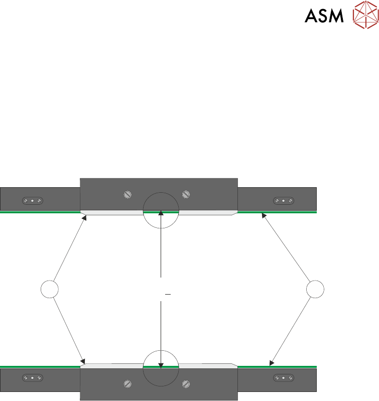
► Place a vernier gauge above the transport belts (1) in the centre of the board clamps (2) and
check that the vernier reads 250.20mm +/-0.05mm.
250.20mm +0.05mm
2 1
► If the rail width is correct, go to Close Up.
Adjustment
► Close the front printhead cover.
► Press the System button.
► Use Next or Previous to highlight Set Rail Board Width Calibration.
► Select Run Diagnost to open the Rail Width Offset window.
► Use Incr. or Decr. to set the offset required to achieve 250.20mm +/-0.05mm.
NOTE
Increasing the offset increases the dimension between the rear rail and the home position there-
fore, decreasing the width between the front and rear rails.
16 TRANSPORT RAILS MODULE
16.4 ADJUSTMENTS AND SETTINGS
252 TECHNICAL REFERENCE MANUAL Vol 1 E By DEK 04/2019
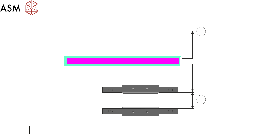
RAIL WIDTH OFFSET 0.00 mm
±3.00mm
3
4
3 Rear of Machine 4 Rail Width
► Select Move.
► Open the front printhead.
► Recheck the measurement.
► If the rail width is incorrect, close the front printhead cover, press the System button and re-
peat Adjustment. If the rail width is correct go to Close Up.
Close Up
► If the rail width is correct, close the front printhead cover, press the System button and select
Set.
► Select Yes to save the information.
► Use Next or Previous to highlight Cycle Board on Belts.
► Select Run Diagnost.
► Place a test board, that matches the rail width, on the transport rails.
► Select Auto Board and ensure the board runs through the entire length of the rail system for
10 complete cycles, without jamming or excessive clicking of the board edges.
NOTE
If any jamming occurs investigate the position of the board/snugger clamps before repeating the
check.
► With the board in the tooling area, use a 0.2mm feeler gauge between the edge of the board
and the snugger plate. If the feeler gauge is either tight or loose adjust the dimension in Set
Rail Board Width Calibration accordingly.
► Select Stop.
► Remove the board from the transport rails.
► Select Exit.
► Select Exit.
► Select Back.
16.4.9 Rail to Table Height
The rail to table height ensures that the board is supported correctly and evenly during the print
process.
NOTE
Rail to Table Height setting is factory set and no attempt should be made to make adjustment. If
the transport rails have been removed from the printer, a coplanarity procedure must be carried out
before commencing printing. Please contact your local customer support office for more detail.