03217917-01-01E By DEK Technical Reference Manual Vol 1_enPDFA.pdf - 第258页
16 TRANSPORT RAILS MODULE 16.5 REPLACEMENT PROCEDURES 258 TECHNICAL REFERENCE MANUAL Vol 1 E By DEK 04/2019 ► On the rear rail, remove the snugger base plate securing screws (6) and remove the snugger base plate (1). ► O…
16 TRANSPORT RAILS MODULE
16.5 REPLACEMENT PROCEDURES
TECHNICAL REFERENCE MANUAL Vol 1 E By DEK 04/2019 257
NOTE
With Auto Rail Width set to Disabled the rear rail does not set the board width, but it can still be
moved in diagnostics.
► Select Maintenance.
► Select Machine Setup.
► Select Basics.
► Select Clamp Type.
► Select Snuggers.
► Select Accept.
► Select Back.
► Select Back.
► Select Back.
► Carry out 16.4.7 "Board to Snugger Gap" [}249].
16.5.4 Snuggers to Board Clamps
WARNING
BOARD CLAMPS. EXTREME CARE MUST BE EXERCISED WHEN WORKING IN
THE TOOLING AREA OF THE MACHINE TO AVOID INJURY. THE FOILS ON THE
FRONT AND REAR BOARD CLAMPS ARE VERY SHARP.
NOTE
This procedure is valid when converting to either board clamps or foil-less clamps.
► Select Open Cover Commands.
► Select Carriage To Rear.
► Select Unload Screen.
► Open the front printhead cover.
► Remove the stencil from the machine.
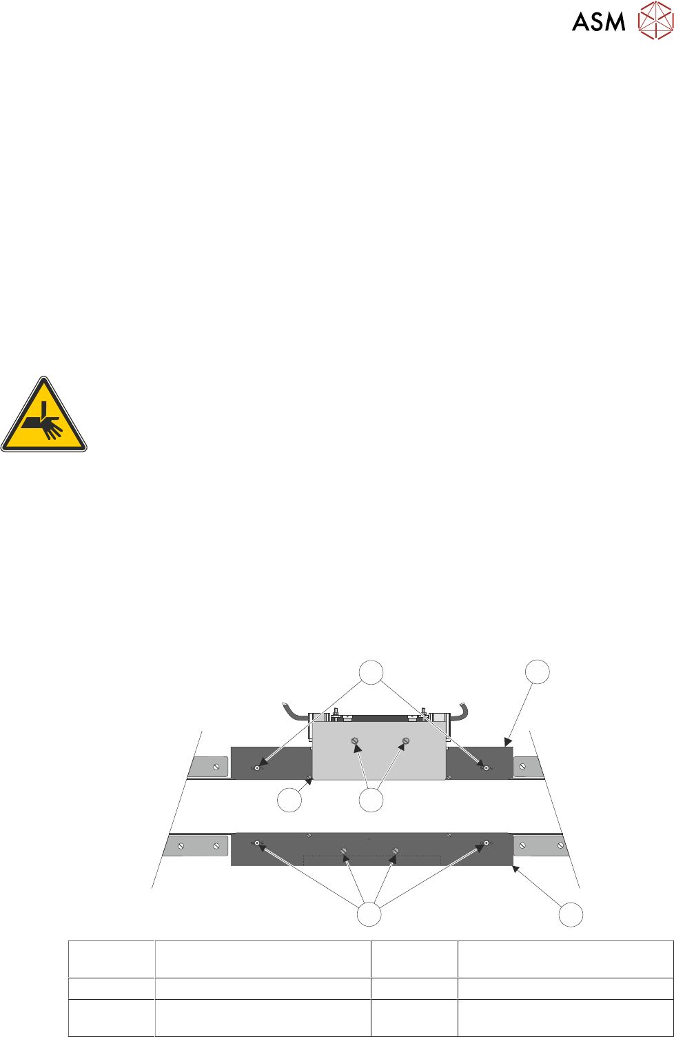
► On the rear rail, remove the two rear snugger plate securing screws (4) and remove the rear
snugger plate (5).
6
4
1
2
3
5
1 Rear Snugger Base Plate 4 Rear Snugger Plate Securing
Screws
2 Front Snugger Plate 5 Rear Snugger Plate
3 Front Snugger Plate Securing
Screws
6 Rear Snugger Base Plate Secur-
ing Screws
16 TRANSPORT RAILS MODULE
16.5 REPLACEMENT PROCEDURES
258 TECHNICAL REFERENCE MANUAL Vol 1 E By DEK 04/2019
► On the rear rail, remove the snugger base plate securing screws (6) and remove the snugger
base plate (1).
► On the front rail, remove the front snugger plate securing screws (3) and remove the front
snugger plate (2).
► Fit the board clamp to the rear rail and secure using the M4 pan head screws.
► Fit the board clamp to the front rail and secure using the M4 pan head screws.
► Foil-less clamps only. Fit the appropriate foil-less clamp to the rear rail and secure using the
M4 pan head screws.
► Foil-less clamps only. Fit the appropriate foil-less clamp to the front rail and secure using the
M4 pan head screws.
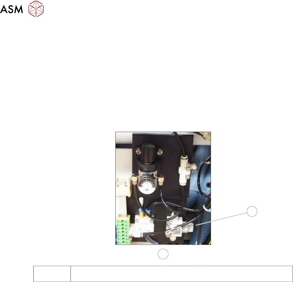
► Locate the magnetic plate on the right hand side of the machine containing the pneumatics for
the snuggers.
7
8
7 Pneumatic Switch 8 View on Right Hand Side of Ma-
chine
► Turn the pneumatic switch (7) On.
► Select Maintenance.
► Select Machine Setup.
► Select Basics.
► Select Clamp Type.
► Select Board Clamps.
► Select Accept.
► Select Back.
► Select Back.
► Select Back.
► Foil-less clamps only. Carry out 16.4.4 "Foil-less Clamp Height Adjustment" [}242].
NOTE
The Board Clamp Setting procedure is not required after snugger to board clamp/foil-less clamp re-
placement.
16 TRANSPORT RAILS MODULE
16.5 REPLACEMENT PROCEDURES
TECHNICAL REFERENCE MANUAL Vol 1 E By DEK 04/2019 259
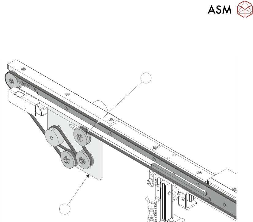
16.5.5 Heavy Board Rails Drive Belt
► Slacken the adjustable idler pulley (1) securing screw, at the rear of the motor bracket (2).
1
2
► Slide the adjustable idler pulley (1) to slacken the drive belt.
► Remove the drive belt and discard.
► Fit the replacement drive belt.
► Using a suitable cable tie, engage a forcemeter with the adjustable idler pulley (1). Apply a ho-
rizontal force of 5.1kg to 6.1kg.
► Maintaining this force, tighten the adjustable idler pulley (1) securing screw.
► Select Maintenance.
► Select Diagnostics.
► Use Next or Previous to highlight Rail System.
► Select Select Module.
► Use Next or Previous to highlight Drive Belts Using Two Button Control.
► Select Run Diagnost.
► Using either the left or right jog button, drive the belt motors for a few seconds to even out the
tension in the belt.
► Recheck the belt tension.
► Select Exit.
► Select Exit.
► Select Back.