03217917-01-01E By DEK Technical Reference Manual Vol 1_enPDFA.pdf - 第260页
16 TRANSPORT RAILS MODULE 16.6 CALIBRATIONS 260 TECHNICAL REFERENCE MANUAL Vol 1 E By DEK 04/2019 16.6 CALIBRATIONS NOTE Where the printer is connected to inline equipment make sure that the FMI functionality is turned O…
16 TRANSPORT RAILS MODULE
16.5 REPLACEMENT PROCEDURES
TECHNICAL REFERENCE MANUAL Vol 1 E By DEK 04/2019 259
16.5.5 Heavy Board Rails Drive Belt
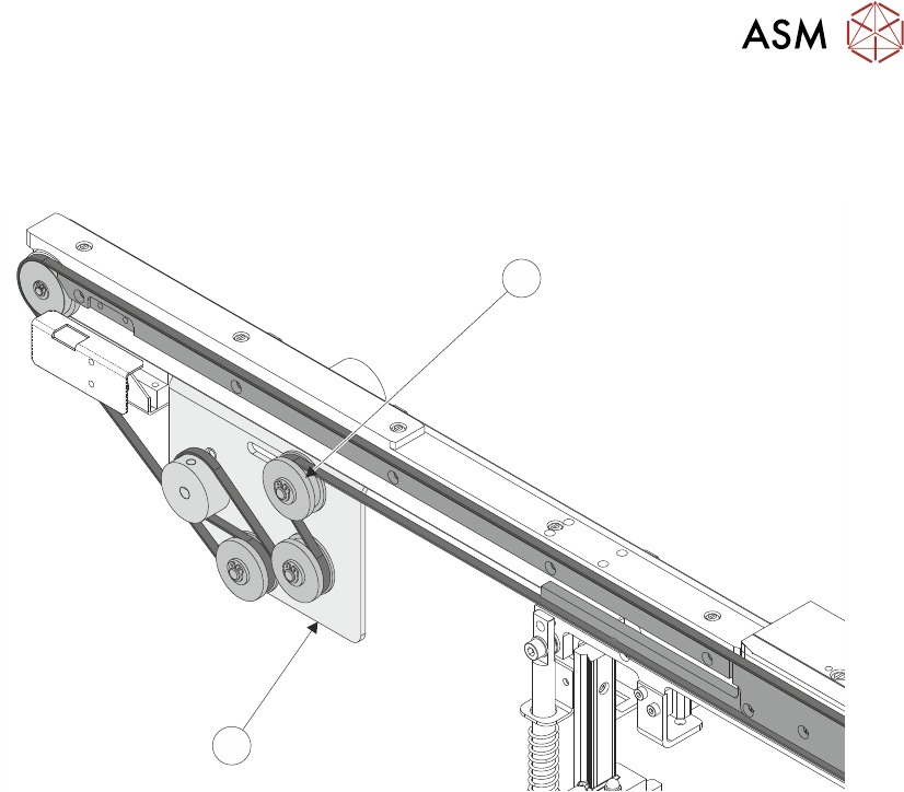
► Slacken the adjustable idler pulley (1) securing screw, at the rear of the motor bracket (2).
1
2
► Slide the adjustable idler pulley (1) to slacken the drive belt.
► Remove the drive belt and discard.
► Fit the replacement drive belt.
► Using a suitable cable tie, engage a forcemeter with the adjustable idler pulley (1). Apply a ho-
rizontal force of 5.1kg to 6.1kg.
► Maintaining this force, tighten the adjustable idler pulley (1) securing screw.
► Select Maintenance.
► Select Diagnostics.
► Use Next or Previous to highlight Rail System.
► Select Select Module.
► Use Next or Previous to highlight Drive Belts Using Two Button Control.
► Select Run Diagnost.
► Using either the left or right jog button, drive the belt motors for a few seconds to even out the
tension in the belt.
► Recheck the belt tension.
► Select Exit.
► Select Exit.
► Select Back.
16 TRANSPORT RAILS MODULE
16.6 CALIBRATIONS
260 TECHNICAL REFERENCE MANUAL Vol 1 E By DEK 04/2019
16.6 CALIBRATIONS
NOTE
Where the printer is connected to inline equipment make sure that the FMI functionality is turned
OFF before proceeding.
The front and rear board transport belts are driven independently by two variable speed motors. In-
evitably one motor drives faster than the other motor. It is necessary to calibrate these motors so
that they drive at the same speed.
Feeder motor speed is measured using a tachometer on the input or output pulley and adjusted by
a potentiometer control on each motor.
16.6.1 Belt Speed Calibration Procedure
► Remove the right hand side safety cover to gain access to the transport belt motors.
► Select Maintenance.
► Select Diagnostics.
► Use Next or Previous to highlight Rail System.
► Select Select Module.
► Use Next or Previous to highlight Belt Speed Calibration.
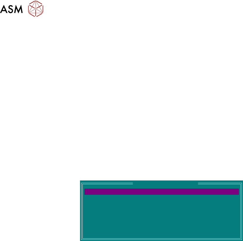
► Select Run Diagnost. The following window is displayed:
Belt Speed Calibration
64
64
64
64
64
64
64
64
FRONT L 2 R SPEED
FRONT R 2 L SPEED
REAR R 2 L SPEED
REAR R 2 L SPEED
FRONT L 2 R ALT SPEED
FRONT R 2 L ALT SPEED
REAR L 2 R ALT SPEED
REAR R 2 L ALT SPEED
NOTE
Belt Speed Calibration figures displayed on this page have no relevance to the belt speeds on the
machine.
► Select Front L 2 R Speed.
► Select Incr. or Decr. to start the belts
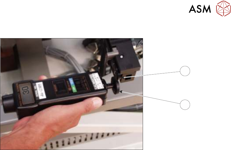
► Using a tachometer fitted with the surface speed test wheel, positioned on the input or output
pulley of the front belt motor, measure the speed of the motor right to left.
NOTE
For heavy board option the ‘Front’ settings refer to the rear rail and the ‘Rear’ settings refer to the
front rail.
16 TRANSPORT RAILS MODULE
16.6 CALIBRATIONS
TECHNICAL REFERENCE MANUAL Vol 1 E By DEK 04/2019 261
1
2
► Ensure that one of the following speeds is achieved:
●
29 to 31 m/min for standard transport rails.
●
37 to 39 m/min for heavy board transport rails.
► Repeat previous two steps for Front R 2 L, Rear L 2 R and Rear R 2 L.
► In the table highlight Front L 2 R ALT Speed.
► Using a tachometer fitted with the surface speed test wheel, positioned on the input or output
pulley of the front belt motor, measure the speed of the motor right to left.
NOTE
For heavy board option the ‘Front’ settings refer to the rear rail and the ‘Rear’ settings refer to the
front rail.
► Select Incr. or Decr. to adjust the motor speed to achieve 14 to 16 m/min.
► Repeat previous two steps for Front R 2 L Alt Speed, Rear L 2 R Alt Speed, and Rear R 2 L
Alt Speed.
► If adjustment is required, remove the belt speed adjuster cap (3) on the appropriate motor and
adjust using a suitable trimming tool.