03217917-01-01E By DEK Technical Reference Manual Vol 1_enPDFA.pdf - 第262页
16 TRANSPORT RAILS MODULE 16.6 CALIBRATIONS 262 TECHNICAL REFERENCE MANUAL Vol 1 E By DEK 04/2019 3 ► Select Next . ► Select Incr. or Decr. to start the belts running left to right. ► Ensure that one of the following spe…
16 TRANSPORT RAILS MODULE
16.6 CALIBRATIONS
TECHNICAL REFERENCE MANUAL Vol 1 E By DEK 04/2019 261
1
2
► Ensure that one of the following speeds is achieved:
●
29 to 31 m/min for standard transport rails.
●
37 to 39 m/min for heavy board transport rails.
► Repeat previous two steps for Front R 2 L, Rear L 2 R and Rear R 2 L.
► In the table highlight Front L 2 R ALT Speed.
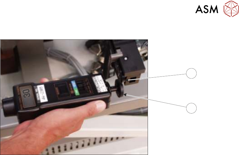
► Using a tachometer fitted with the surface speed test wheel, positioned on the input or output
pulley of the front belt motor, measure the speed of the motor right to left.
NOTE
For heavy board option the ‘Front’ settings refer to the rear rail and the ‘Rear’ settings refer to the
front rail.
► Select Incr. or Decr. to adjust the motor speed to achieve 14 to 16 m/min.
► Repeat previous two steps for Front R 2 L Alt Speed, Rear L 2 R Alt Speed, and Rear R 2 L
Alt Speed.
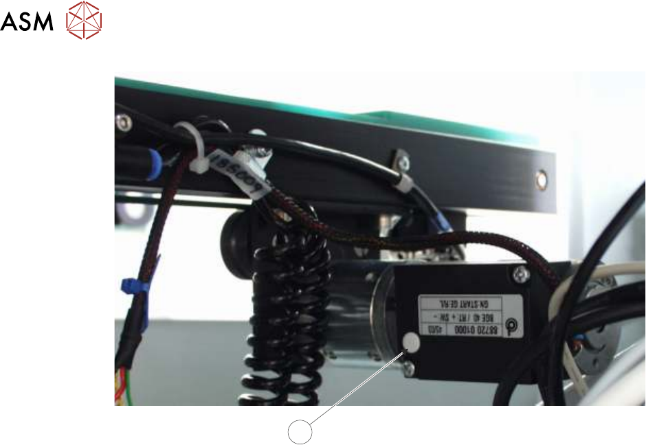
► If adjustment is required, remove the belt speed adjuster cap (3) on the appropriate motor and
adjust using a suitable trimming tool.
16 TRANSPORT RAILS MODULE
16.6 CALIBRATIONS
262 TECHNICAL REFERENCE MANUAL Vol 1 E By DEK 04/2019
3
► Select Next.
► Select Incr. or Decr. to start the belts running left to right.
► Ensure that one of the following speeds is achieved for both the front and rear belts:
●
29 to 31 metres/min for standard transport rails.
●
37 to 39 metres/min for heavy board transport rails.
NOTE
There is no separate adjustment between left to right and right to left. If the above speed is not
achievable in both directions, the motor may be faulty.
► Select Exit.
► Select Exit.
► Select Back.
► Refit the safety cover.
17 CAMERA SYSTEM MODULE
17.1 OVERVIEW
TECHNICAL REFERENCE MANUAL Vol 1 E By DEK 04/2019 263
17
CAMERA SYSTEM MODULE
17.1 OVERVIEW
1
2
3
4
5
6
7
8
9
10
11
12
13
14
15
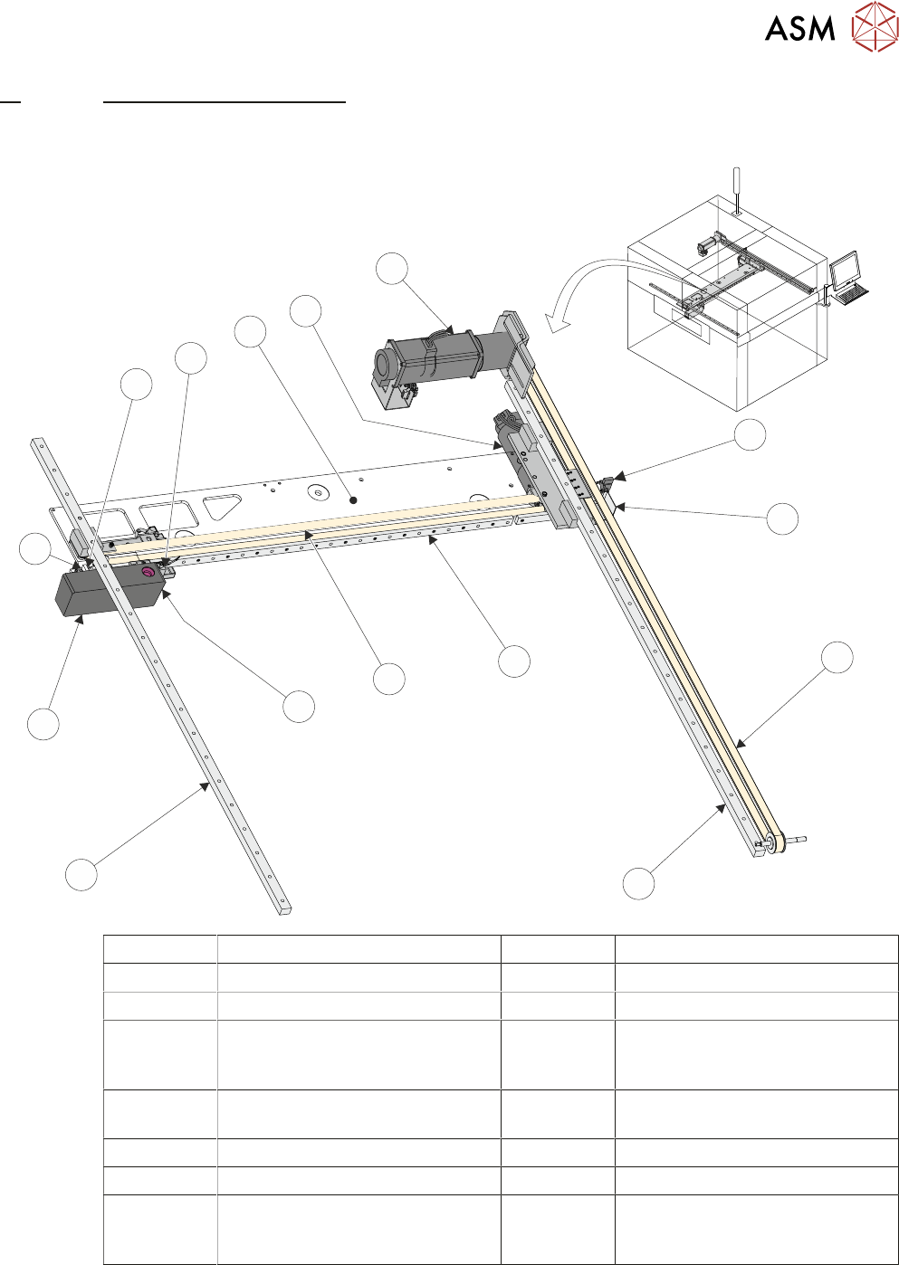
1 Camera Y Home Sensor 9 Camera Assembly
2 Camera Y Home Vane 10 Camera X Home Vane
3 Y Axis Drive Belt 11 Camera X Home Sensor
4 Y Axis Right Hand Linear Bearing
(mounted on bottom of right hand
printhead)
12 Camera Mounted Board Stop and
Board Stop Extended Sensor
5 X Axis Linear Bearing 13 Camera X Axis Support Platform
(shown transparent for clarity)
6 X Axis Timing Belt 14 Camera X Motor Node 8
7 Board at Stop Sensor 15 Camera Y Motor Node 9
8 Y Axis Left Hand Linear Bearing
(mounted on bottom of Left hand
printhead)