03217917-01-01E By DEK Technical Reference Manual Vol 1_enPDFA.pdf - 第265页
17 CAMERA SYSTEM MODULE 17.2 ELECTRICAL SCHEMATIC TECHNICAL REFERENCE MANUAL Vol 1 E By DEK 04/2019 265 17.2 ELECTRICAL SCHEMATIC M37 Power Supply Module Power Distribution P C B C A N T erminator N8S K 2 Camera X Motor …

17 CAMERA SYSTEM MODULE
17.1 OVERVIEW
264 TECHNICAL REFERENCE MANUAL Vol 1 E By DEK 04/2019
The camera assembly traverses horizontally in the X and Y axis to position the camera to carry out
the following functions:
●
Board Stop
●
Fiducial Capture - for stencil to board alignment
●
Site Capture - pre and post printing for 2Di inspection
●
Moving the Underscreen Cleaner
Positioning of the camera assembly is carried out by the X and Y drive mechanisms.
The camera contains an optical unit for image focusing and a lighting unit for board and stencil illu-
mination during fiducial and 2D camera capture operations.
The camera carriage also contains the following:
●
Camera Board Stop
●
Board at Stop sensor
●
Board Stop Extended Sensor
The camera board stop is a pneumatically driven unit which is lowered to stop the board in position
ready for clamping and vision alignment to take place.
The board at stop diffuse background suppressed opto detects the board when it reaches the
board stop. This starts a timer which when elapsed stops the belts and clamps the board.
The board stop extended sensor is fitted to ensure that the board stop is raised before any camera
carriage movement is demanded.
The camera positions are referenced from the home position. Each camera axis only homes during
initialisation, which can be from power-up or exiting diagnostics.
The camera system also provides the drive mechanism for the under screen cleaner.
The camera used by the camera system is the Hawkeye 750.
17 CAMERA SYSTEM MODULE
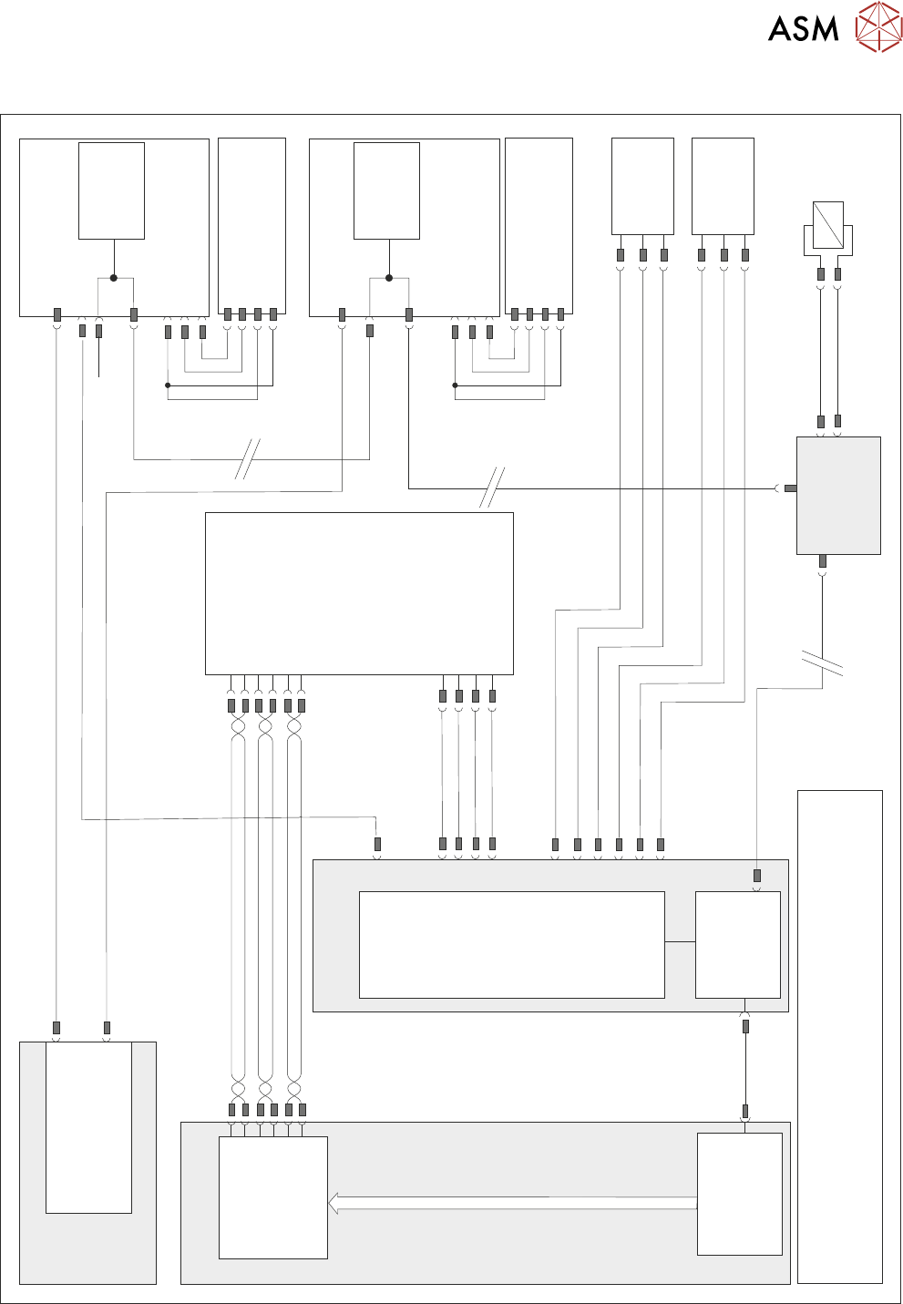
17.2 ELECTRICAL SCHEMATIC
TECHNICAL REFERENCE MANUAL Vol 1 E By DEK 04/2019 265
17.2 ELECTRICAL SCHEMATIC
M37 Power Supply Module
Power Distribution
PCB
CAN Terminator
N8SK2
Camera X Motor
Node 8
M37PL18
Servo DC Supply & 24V US (Motor Logic)
N8PL1
N8PL4
DIG IN 2
DIG IN 2
0V
0V
Signal
Signal
24V
24V
(L)
(L)
Camera X
Home 10SE01
Fork Opto
CAN
Encoder/
Decoder
N8SK3
CAN In
Camera Y Motor
Node 9
N9PL1
N9PL4
Camera Y
Home 10SE02
Fork Opto
CAN
Encoder/
Decoder
N9SK3
CAN In
CAN Out
M37PL19
PC
P
C
I
B
u
s
Motherboard
USB
Servo DC Supply & 24V US (Motor Logic)
N9SK2
M36 Machine
Control Enclosure
NextMove
Interface
NextMove ES
(I/O Node 1)
M36PL35
CAN Bus
Main Machine
I/O Node 2
N2SK2
CAN In
16SK14
16SOL14
Board
Stop
DIG OUT 10
N2PL4
0V
CAN
Out
N2SK3
Board Stop
Extended
10SE20
Board At
Stop
10SE07
10SK24
M36PL11
0V
+12V
DIG IN 8
+12V
0V
DIG IN 9
NOTE
The breaks in the CAN Bus chain reflect that additional I/O Nodes
may be fitted, refer to Machine Control chapter for the complete
CAN Bus chain.
Power
3PL55
GND
TP B-
TP B+
TP A-
TP A+
Digital
Camera
10PL17
10SK13
PCI Interface
Card
M36PL16
M36PL5
Trigger
0V
+24V US
0V

17 CAMERA SYSTEM MODULE
17.3 ADJUSTMENTS AND SETTINGS
266 TECHNICAL REFERENCE MANUAL Vol 1 E By DEK 04/2019
17.3 ADJUSTMENTS AND SETTINGS
17.3.1 X Camera Home Positioning
The position of the sensor and vane is fixed, therefore no adjustment is possible.
17.3.2 Y Camera Home Positioning
The position of the sensor and vane is fixed, therefore no adjustment is possible.
17.3.3 X Axis Parallelism
WARNING
BOARD CLAMPS. EXTREME CARE MUST BE EXERCISED WHEN WORKING IN
THE TOOLING AREA OF THE MACHINE TO AVOID INJURY. THE FOILS ON THE
FRONT AND REAR BOARD CLAMPS ARE VERY SHARP.
NOTE
The X axis parallelism is factory set and shouldn’t normally need to be adjusted.
► Select Open Cover Commands.
► Select Carriage To Rear.
► Select Unload Screen.
► Open the printhead cover.
► Remove the stencil from the machine.
► Close the printhead cover.
► Press the System button.
► Select Back.
► Select Maintenance.
► Select Diagnostics.
► Using the Next or Previous button highlight Rail System.
► Select Select Module.
► Ensure that Home Rail Width is highlighted.
► Select Run Diagnost.
► Select Exit.
► Using the Next or Previous button highlight Rising Table.
► Select Select Module.
► Using the Next or Previous button highlight Raise Table to Vision Height.
► Select Run Diagnost.
► Select Exit.
► Using the Next or Previous button highlight Rail System.
► Select Select Module. The board clamps are released.
► Open the printhead cover.
► Remove any tooling from the manual tooling plate.
► Remove the board clamp from the front transport rail, see 16.5.1 "Board Clamp Replace-
ment" [}253].