03217917-01-01E By DEK Technical Reference Manual Vol 1_enPDFA.pdf - 第28页
3 SAFETY FEATURES 3.2 GENERAL 28 TECHNICAL REFERENCE MANUAL Vol 1 E By DEK 04/2019 3.2.1 Emergency Stop (E Stop) The machine is fitted with an E Stop which suspends all machine operations. The switch is within easy reach…
3 SAFETY FEATURES
3.2 GENERAL
TECHNICAL REFERENCE MANUAL Vol 1 E By DEK 04/2019 27
3.2 GENERAL
DEK printing machines incorporate safety features that provide a safe operating environment for
the operator and the machine.
All safety circuits have been designed to meet the safety requirements as outlined in the machines’
CE Declaration of Conformity. The circuits check for welded contacts before resetting. Additional
safety is achieved by duplication of the power contactors to provide redundancy.
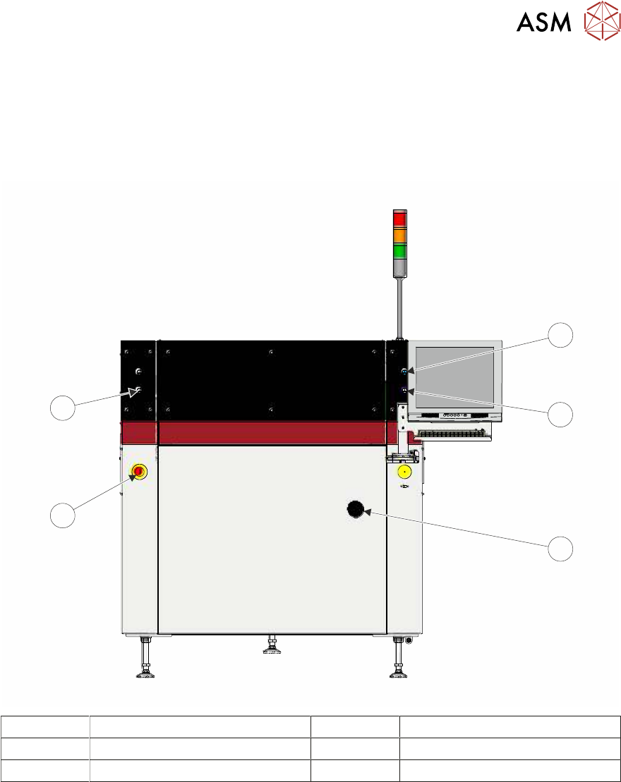
1
2
3
4
5
1 System Button 4 E Stop Button
2 Right Jog Button 5 Left Jog Button
3 Mains Isolator Switch
3 SAFETY FEATURES
3.2 GENERAL
28 TECHNICAL REFERENCE MANUAL Vol 1 E By DEK 04/2019
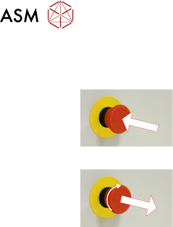
3.2.1 Emergency Stop (E Stop)
The machine is fitted with an E Stop which suspends all machine operations. The switch is within
easy reach of the operator and once pressed, the latching switch requires resetting.
To reset the E Stop, turn the button clockwise until it unlatches.
Pressing the E Stop or opening the printhead cover cuts the servo axes power supply. A warning of
this condition is reported on the machine monitor.
3.2.1.1 E Stop Module Shut Down
If the E Stop loop is opened by pressing the E Stop or opening the printhead cover, an emergency
stop is initiated via the E Stop module. When actuated the following areas of the machine are
rendered inactive:
●
Lid Bolt
●
Moving Rail Stepper
●
Print Carriage Servo (axis stopped before power is removed)
●
Rail System Front and Rear Belt Motor Drives
●
Rising Table Brake (brake engages when power is cut)
●
Rising Table Servo
●
Squeegee Stepper Motor(s)
●
System Lamp
●
Understencil Cleaner Paper Feed Motor
●
Understencil Cleaner Solvent Pump
●
Understencil Cleaner Squeegee Solenoid
●
Vacuum Tooling Solenoid
●
X Camera Motor (axis stopped before power is removed)
●
X Forward, X Rear and Y Chase Alignment Stepper Motors
●
Y Camera Motor (axis stopped before power is removed)
3.2.1.2 Recovery
When normal working conditions are restored, release the E Stop switch and, when prompted by a
screen message, press the System button.

3 SAFETY FEATURES
3.2 GENERAL
TECHNICAL REFERENCE MANUAL Vol 1 E By DEK 04/2019 29
3.2.2 Opening Covers
Opening printhead covers are fitted with a cam interlock switch to protect personnel from internal
moving parts.
3.2.2.1 Lid Bolt
Lid bolts are fitted to all opening printhead covers to prevent them from being raised during the
print cycle.
The lid bolts are withdrawn and the printhead cover may be raised when:
●
Open Cover is requested by software
●
Pause or stop is selected during a print cycle
●
The E Stop is pressed
3.2.3 Jog Buttons
The two button control switches or jog buttons are positioned such as to maintain maximum safety
for the operator whilst solvent priming or paper feeding with the printhead cover open. This requires
both buttons to be depressed simultaneously for the function to become active. The use of these
buttons is dependent on the function selected on the machine monitor. During normal operation
these buttons control paper feed and solvent prime operations. When in maintenance mode, the
two button control switches control the movement of the following diagnostics:
●
Print Carriage
●
Squeegee Assembly
●
Camera Axes
●
Rail System
●
Screen Alignment
●
Rising Table
Only one button is required to drive the selected mechanism, the two buttons are used to drive the
mechanism in opposite directions, ie jog forward or jog back.