03217917-01-01E By DEK Technical Reference Manual Vol 1_enPDFA.pdf - 第282页
17 CAMERA SYSTEM MODULE 17.5 CALIBRATIONS AND CHECKS 282 TECHNICAL REFERENCE MANUAL Vol 1 E By DEK 04/2019 17.5 CALIBRATIONS AND CHECKS 17.5.1 Board Stop X Offset Check W ARNING BOARD CLAMPS. EXTREME CARE MUST BE EXERCIS…
17 CAMERA SYSTEM MODULE
17.4 REPLACEMENT PROCEDURES
TECHNICAL REFERENCE MANUAL Vol 1 E By DEK 04/2019 281
11
3
10
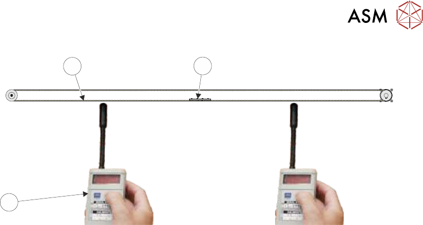
► Using a tension meter (Part No. 190279), check the timing belt tension either side of the cable
clamp is between 42Hz and 48Hz. Check the two readings are within 1Hz of each other.
NOTE
Adjust the position (between the two pulleys) of the belt clamp to achieve the 1Hz deviation.
► If adjustment is not required, go to Correct Tension.
► If adjustment is required, slacken the two securing screws as detailed in Step 9.
► Adjust the timing belt tension using the cable tie.
► Tighten the locknut.
► Repeat until the correct tension is achieved.
► Correct Tension - Remove the timing belt clamp securing screws one at a time, apply a suit-
able locking compound and fully tighten.
► Remove the cable tie.
► Refit the panels removed.
► Remove the lock from the isolator.
► Power up the machine.
► Select Maintenance.
► Select Diagnostics.
► Using the Next or Previous button highlight Camera Axes.
► Select Select Module.
► Using the Next or Previous button highlight Home Camera X Axis.
► Select Run Diagnost.
► Using the Next or Previous button highlight Home Camera Y Axis.
► Select Run Diagnost.
► Carry out the following checks:
1. Camera Reference Position.
2. Calibrate Vision.

17 CAMERA SYSTEM MODULE
17.5 CALIBRATIONS AND CHECKS
282 TECHNICAL REFERENCE MANUAL Vol 1 E By DEK 04/2019
17.5 CALIBRATIONS AND CHECKS
17.5.1 Board Stop X Offset Check
WARNING
BOARD CLAMPS. EXTREME CARE MUST BE EXERCISED WHEN WORKING IN
THE TOOLING AREA OF THE MACHINE TO AVOID INJURY. THE FOILS ON THE
FRONT AND REAR BOARD CLAMPS ARE VERY SHARP.
► Select Open Cover Commands.
► Select Carriage To Rear.
► Select Unload Screen.
► Open the printhead cover.
► Remove the stencil.
► Close the printhead cover.
► Press the System button.
► Select Back.
► Select Maintenance.
► Select Diagnostics.
► Using the Next or Previous button highlight Camera Axes.
► Select Select Module.
► Using the Next or Previous button highlight Home Camera X Axis.
► Select Run Diagnost.
► Using the Next or Previous button highlight Home Camera Y Axis.
► Select Run Diagnost.
► Using the Next or Previous button highlight Drive to Board Stop Position.
► Select Run Diagnost.
► Select Exit.
► Using the Next or Previous button highlight Rail System.
► Select Select Module.
► Using the Next or Previous button highlight Toggle Board Stop.
► Select Run Diagnost.
► Open the printhead cover.
► Place a board onto the rails and move it up against the board stop.
► Close the printhead cover.
► Press the System button.
► Using the Next or Previous button highlight Toggle Board Clamp.
► Select Run Diagnost.
► Using the Next or Previous button highlight Toggle Board Stop.
► Select Run Diagnost.
► Select Exit.
► Using the Next or Previous button highlight Camera Axes.
► Select Select Module.
► Using the Next or Previous button highlight Initialise Vision System.
► Select Run Diagnost.
► Select Exit.
► Open the printhead cover.
17 CAMERA SYSTEM MODULE
17.5 CALIBRATIONS AND CHECKS
TECHNICAL REFERENCE MANUAL Vol 1 E By DEK 04/2019 283
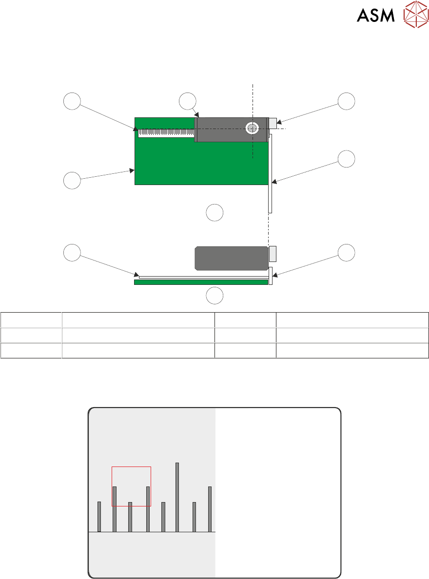
► Place a non-magnetic rule flat against the board edge and slide a second rule so that it abuts
it and comes within the camera field of view.
1
2
2
B
A
2
3
2
4
A Plan View 2 Metric Ruler
B Side View 3 Board
1 Camera Board Stop 4 Camera
► On the vision monitor, record the distance from the board edge to the approximate centre of
the square (figure below refers). This value is the Board Stop X Offset and should be
-43.5mm ±0.5mm.
45
43 4644
NOTE
The numerals on the rule may not be directly in the field of view, move the rule until the numerals
are visible in the vision window. Lay the rule flat on the board, do not lift or angle it as this can dis-
tort the measurement. As the board stop is before the camera the distance is recorded as a minus
reading.
► Remove the rule from the machine.
► Close the printhead cover.
► Press the System button.
► Select Exit.
► During Initialisation, remove the board from the transport rails when prompted.