03217917-01-01E By DEK Technical Reference Manual Vol 1_enPDFA.pdf - 第42页
4 COVERS 4.1 PRINTER COVERS 42 TECHNICAL REFERENCE MANUAL Vol 1 E By DEK 04/2019 4.1.1.8 Upper Front Corner Panels To remove the upper front corner panels, carry out the following: ► Open the front printhead cover. ► Loc…
4 COVERS
4.1 PRINTER COVERS
TECHNICAL REFERENCE MANUAL Vol 1 E By DEK 04/2019 41
4.1.1.7 Rear Corner Panels
To remove either of the rear corner panels, carry out the following:
► Remove the Left Hand Safety Cover (as detailed previously).
► Remove the Right Hand Safety Cover (as detailed previously).
► Using a 4mm Allen key, undo the appropriate four captive screws (1).
► Lift the panel clear of the printer frame, taking care not to damage the earth cable.
1
4 COVERS
4.1 PRINTER COVERS
42 TECHNICAL REFERENCE MANUAL Vol 1 E By DEK 04/2019
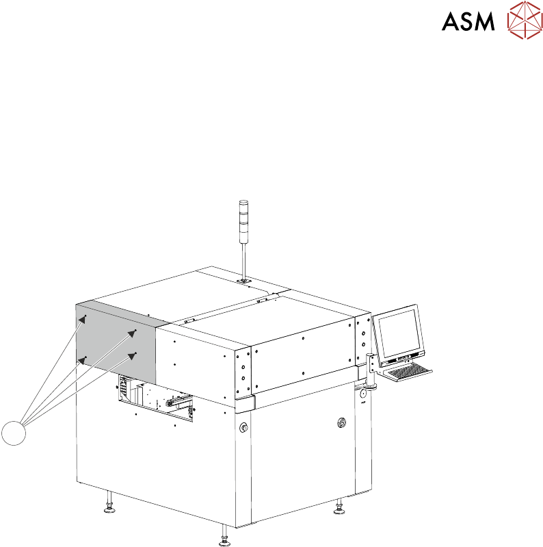
4.1.1.8 Upper Front Corner Panels
To remove the upper front corner panels, carry out the following:
► Open the front printhead cover.
► Locate the control switches (jog switch and system switch) attached to the panel.
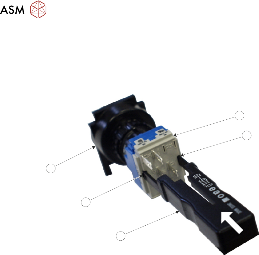
► To disconnect the system switch and jog buttons carry out the following:
► Locate the two release slots (2) in the contact assembly (1) part of the switch.
3
2
4
2
1
► Insert the switch release tool (Part No 188647) (3) into the slots and push until the release tool
clicks into place.
► Leaving the switch release tool in position, pull the contact assembly (1) from the switch body
(4).
► Remove the switch release tool (3) from the contact assembly.
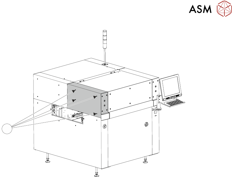
► Using a 4mm Allen key, undo the appropriate four captive screws (5).
► Remove the panel clear of the machine, taking care not to damage the earth cable.
4 COVERS
4.1 PRINTER COVERS
TECHNICAL REFERENCE MANUAL Vol 1 E By DEK 04/2019 43
5
NOTE
To refit the contact assembly to the switch body, using the two keyway slots, push the two units to-
gether until they click into place.