03217917-01-01E By DEK Technical Reference Manual Vol 1_enPDFA.pdf - 第60页
5 MACHINE OVERVIEW 5.3 ELECTRICAL SCHEMATIC 60 TECHNICAL REFERENCE MANUAL Vol 1 E By DEK 04/2019 5.3 ELECTRICAL SCHEMATIC X Forward Actuator X Rear Actuator U SB U SB U SB P C Motherboard M36 Machine Control Enclosure Ne…

5 MACHINE OVERVIEW
5.2 MACHINE PRINT CYCLE
TECHNICAL REFERENCE MANUAL Vol 1 E By DEK 04/2019 59
5.2 MACHINE PRINT CYCLE
The following, is a typical machine print cycle, with camera mounted board stop and squeegees
used as the paste applicator system:
1. Print is selected, the printhead cover lock is engaged and the rising table carries out a rail lif-
ted check.
2. The camera positions itself at the board stop co-ordinates.
3. The print carriage moves to the start of the print stroke and both squeegees drive to their set
dwell height. The chase clamps are energized, clamping the chase in position.
4. The board is transported into the machine stopping at the board stop.
5. The transport belts stop running as soon as the board stop sensor detects the board.
6. The board clamp mechanism operates, clamping the board in position and the board stop re-
tracts.
7. The camera carriage drives to the position determined by Fiducial 1 X and Y co-ordinates.
8. The print carriage is driven to its enhanced start position and the appropriate squeegee is
driven down to start height.
9. The rising table carries out a rail lift check and drives up to vision height.
10. The vision data window displays the board fiducial on the left and the stencil fiducial on the
right of the split display.
11. The fiducials are located and a small blue cross with the fiducial outline appears in the centre
of each fiducial on the split display indicating successful location.
12. While the camera drives to Fiducial 2 X and Y co-ordinates, the location of the Fiducial 1
board and stencil fiducials are copied to the align data structure.
13. Fiducial 2 board and stencil fiducials are located.
14. The chase clamps are de-energised and the screen actuators carry out a rough alignment on
the screen. The chase clamps are re-applied securing the screen.
15. The camera relocates Fiducial 1 and 2. On completion, the camera carriage drives to its home
position.
16. The chase clamps are de-energised and fine alignment on the screen is carried out. On com-
pletion, the chase clamps are re-applied.
17. The relevant squeegee is driven down to make contact with the screen with 0.5kg force.
18. The rising table drives up to the print height.
19. The appropriate squeegee is driven down to the calculated pressure setting, as set in the
board parameter menu.
20. The print carriage drives in the appropriate direction to perform a print stroke.
21. The squeegee mechanism releases full pressure but keeps the squeegee in contact with the
stencil with 0.5kg force (hold height).
22. The rising table is lowered to separation distance at separation speed. Once separation dis-
tance has been reached the rising table accelerates to its normal speed, lowering the table to
transport height. The board clamps are released and the relevant squeegee is raised to dwell
height.
23. The front and rear transport belts drive until the board is detected at the output sensor and the
chase clamps are released.
24. The board count and stencil cleaner cycle counts are incremented. If the stencil cleaner count
has reached the value set by the clean stencil rate, the appropriate cycle is performed.
5 MACHINE OVERVIEW
5.3 ELECTRICAL SCHEMATIC
60 TECHNICAL REFERENCE MANUAL Vol 1 E By DEK 04/2019
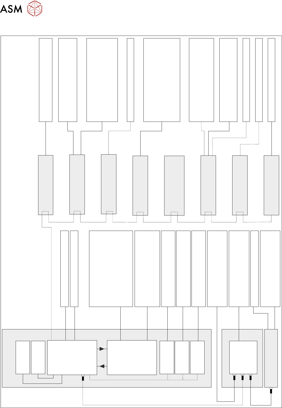
5.3 ELECTRICAL SCHEMATIC
X Forward Actuator
X Rear Actuator
USB
USB
USB
PC
Motherboard
M36 Machine
Control Enclosure
NextMove
Interface
Dual Stepper
Card X3
Dual Stepper
Card X2
Dual Stepper
Card X1
NextMove ES
(I/O Node 1)
I/Ps O/Ps
CAN Bus
O/Ps
O/Ps
I/Os
Front Squeegee Motor
Rear Squeegee Motor
Y Actuator
Moving Rail Motor
M37 Power
Supply Module
O/P
I/Ps
O/Ps
Camera Trigger
Transport Belt Motors
FMI
E Stop Power
I/Ps
Squeegee Home Sensors
Transport Rail Sensors
Board Stop Sensors
Jog Buttons (via M37)
Cover Interlock
FMI
Power ‘ON’ Monitor
System Switch
Jog Buttons
E Stop
MMI Touchscreen (Option)
Keyboard/Mouse
USB Flash Drive
Host Comms
DEK Interactiv
Camera System (vision)
Aout
Temperature to ECM
Ain
O/Ps
USC Solvent Level
System Lamp
Board Stop
Chase/Screen/Board Clamps
Lid Bolt
Tricolour Beacon
USC Cleaner Squeegee
Vacuum Tooling Power
Air Pressure Sensor
Lid Bolt Sensor
Screen Sensor
Vacuum Tooling Sensor
Camera Y Home
Print Carriage Home Sensor
Servo Node 8
(Camera X)
Camera X Home
USC Sensors
USC Home Clamps
USC Motors and Solvent Pump
Vacuum Power
Drip Tray Solenoid
Paste Height Laser
Screen Actuator
Servo Node 6
(Rising Table Motor)
I/O Node 3 Board
(Print Carriage)
Servo Node 7
(Print Carriage Motor)
Servo Node 7
(Print Carriage Motor)
I/O Node 2 Board
(Main Machine)
Various Rail Stepper
Nodes (see Machine
Control chapter)
Servo Node 9
(Camera Y)
I/O Node 4 Board
(Screen Cleaner)
EuroFlex
Card X7
EuroFlex
Card X6
Rising Table Motor
Rising Table Home Sensor
Drip Tray Sensor
Paste Roll Low
Screen Cylinder Sensors
Screen Position Sensor
Squeegee Pressure
6 POWER SUPPLY M37
6.1 OVERVIEW
TECHNICAL REFERENCE MANUAL Vol 1 E By DEK 04/2019 61
6
POWER SUPPLY M37
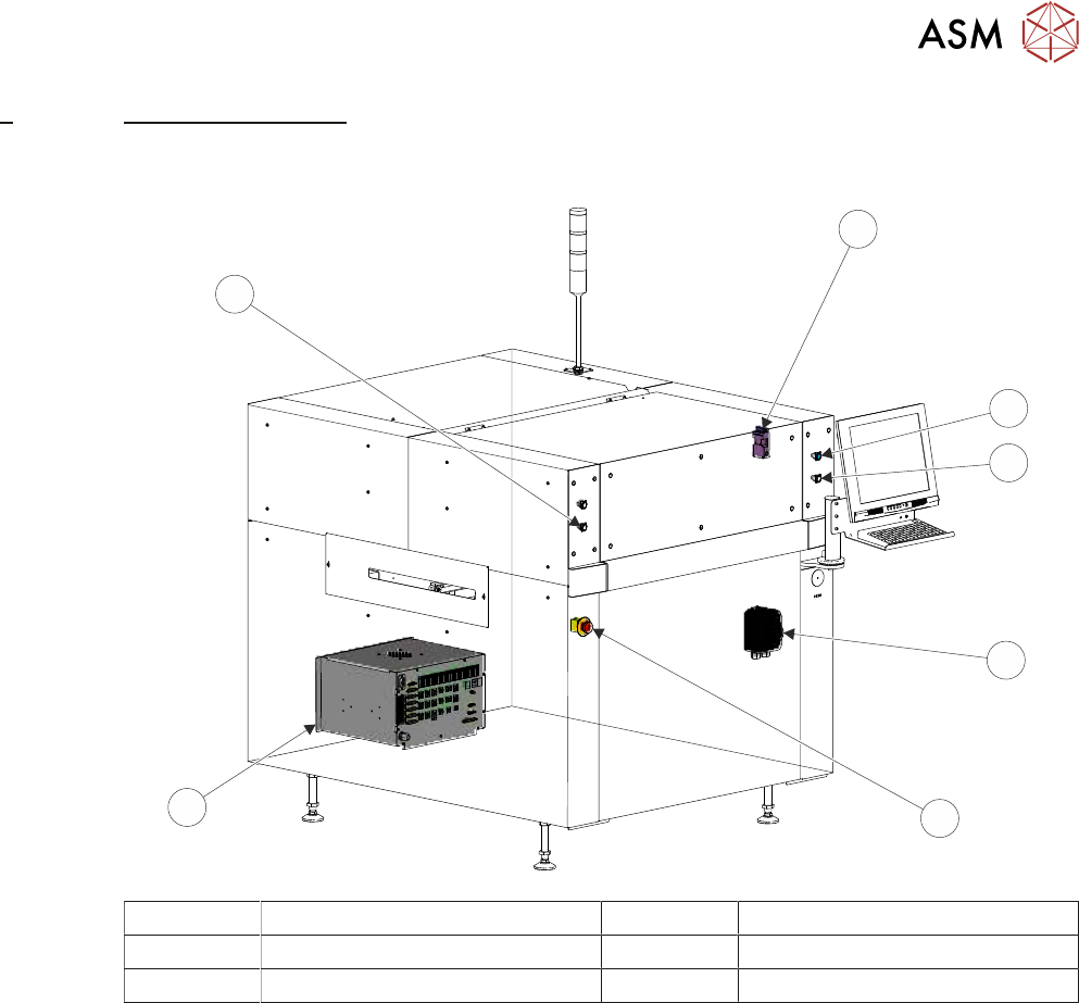
6.1 OVERVIEW
3
6
5
4
3
2
1
1 Front Printhead Cover Interlock 4 Mains Isolator Switch
2 System Button 5 E Stop Button
3 Two Button Control 6 M37 Power Supply Enclosure
Mains input power (100V to 240V) to the machine is routed to the mains isolator switch at the front
of the machine. From the mains isolator it is fed to the M37 power supply crate, through the cable
gland at the rear panel, to the three terminal blocks TB1 (live), TB2 (neutral) and TB3 (earth). From
the terminal blocks mains power is supplied to the following:
●
M37SK31 PC Supply
●
M37SK32 Monitor Supply
●
M37SK33 Spare
●
M37SK34 Spare
●
M37SK35 Internal Vac Pump via Mains Filter and CB34
●
PSU