03217917-01-01E By DEK Technical Reference Manual Vol 1_enPDFA.pdf - 第80页
7 MACHINE PC (STANDARD) 7.2 ELECTRICAL SCHEMATIC 80 TECHNICAL REFERENCE MANUAL Vol 1 E By DEK 04/2019 7.2 ELECTRICAL SCHEMATIC 6S K13 M36P L16 M36P L28 M37P L30 M37P L31 10S K17 10S K13 HD D FAN 3S K01 PS U SAT A Mains I…
7 MACHINE PC (STANDARD)
7.1 OVERVIEW
TECHNICAL REFERENCE MANUAL Vol 1 E By DEK 04/2019 79
7
MACHINE PC (STANDARD)
7.1 OVERVIEW
0
7
1
2
3
4
5
6
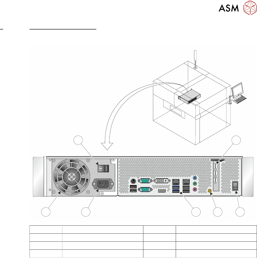
1 PCI Interface Card 5 Mains Input Connector
2 Reset Switch 6 Cooling Fan
3 Earth Bonding Connector 7 Mains Power On/Off Switch
4 Peripheral Connector Panel
The machine PC handles all the machine functions (via CAN Bus and LAN Host Comms), printer
cameras and the MMI.
7 MACHINE PC (STANDARD)
7.2 ELECTRICAL SCHEMATIC
80 TECHNICAL REFERENCE MANUAL Vol 1 E By DEK 04/2019
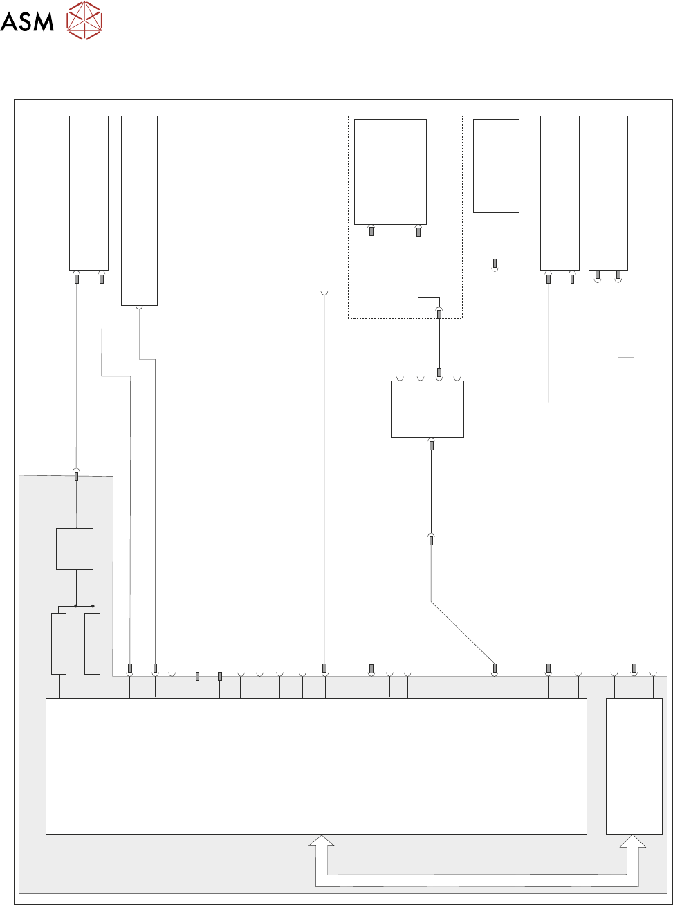
7.2 ELECTRICAL SCHEMATIC
6SK13
M36PL16
M36PL28
M37PL30
M37PL31
10SK17
10SK13
HDD
FAN
3SK01
PSU
SATA
Mains In
PCI Bus
3PL02a
MMI
DVI-I
14SK04
14SK03
4PL1
4 Port
USB Hub
4SK3
4SK2
4SK4
8SK38
8SK37
Line Out
3SK47 - Not Used
Line In
Mic In
3PL05
DVI-I
3PL55
USB3
3PL35
3PL02b Not Used
3SK63 - Not Used
3PL54 - Not Used
3PL53 - Not Used
Operator USB Connector (Right hand)
3SK48 - Not Used
3SK49 - Not Used
3SK34 - Not UsedUSB2
HDMI
PS2 - 6 Pin Mini Keyboard
3SK04 - Not Used
USB4
USB2
3SK36 - Dongle
3PL56
COM 2 RS232
COM 1 RS232
LAN2 Host Comms
LAN1 Host Comms
USB6
3PL37
3PL03a - (Stinger if fitted)
IEEE 1394a (400)
PCI Interface Card
Motherboard
PC Enclosure
Machine Control Enclosure
Digital Camera Module
Monitor
Touchscreen Option
Rear Service Panel
Host Comms RJ45 Ethernet LAN Port
Power Supply Enclosure
3PL03b - Not Used
Keyboard/Mouse
USB1
3PL56
Touchscreen Option

7 MACHINE PC (STANDARD)
7.3 PC ENCLOSURE
TECHNICAL REFERENCE MANUAL Vol 1 E By DEK 04/2019 81
7.3 PC ENCLOSURE
7.3.1 Motherboard System
This card provides the master control of all machine functions, it houses the Central Processing
Unit (CPU) which is an Intel® Celeron® processor G1820 2.7GHz.
The main features of this card are:
●
DVI Output ( using VGA Adaptor)
●
HDMI Output - Not Used
●
6 USB Ports
●
Ethernet 10/100Base-T output via an RJ45 connector to LAN1 Host Comms
●
LAN2 Host Comms - Not Connected
●
SATA HDD fixed disk controllers
●
2 PCI Bus Interface
●
RS232 Interface (COM1) - Not Connected
●
RS232 Interface (COM2) - Not Connected
●
CMOS RAM with Lithium battery backup (Not Shown)
●
6 Pin Mini Keyboard Connector - Not Used
●
4 DDR2 DIMM Sockets (RAM) (Not Shown)
●
Line Out Connector - Not Used
●
Line In Connector - Not Used
●
Mic In - Not Used
7.3.2 BIOS Settings
The BIOS settings are password protected to prevent any settings being changed.
It is highly unlikely that the BIOS settings could be responsible for PC issues however, if the set-
tings are strongly suspected, contact the CSG Helpdesk.