CP-7[732-742]-series Mechanical Reference(2.9E).pdf - 第12页
Safety Guidelines Fuji machines are designed and pr oduced with safety as one of our main considerations. However , even a perfectly designed machine can be damaged, or someone can still be injured if the user does not f…

1.10.2 Adjusting the Nozzle UP Limit Sensors...............................................4-1-30
1.10.3 Adjusting the Nozzle DOWN Limit Sensors.........................................4-1-32
1.11 Mechanical Valve Switching (Station 9).......................................................4-1-34
1.11.1 Checking the Position of the Pin Bracket ............................................4-1-34
1.11.2 Valve Switching Lever Height Adjustment...........................................4-1-35
1.12 Reverse-theta Mechanism (Station 10).......................................................4-1-37
1.12.1 Clutch Meshing Check.........................................................................4-1-37
1.12.2 Clutch Meshing Check Sensor Position Adjustment ...........................4-1-38
1.12.3 Clutch Meshing Check Sensor Amp Adjustment.................................4-1-39
1.13 Mechanical Valve Switching (Station 13).....................................................4-1-40
1.13.1 Valve Switching Unit Position Adjustment...........................................4-1-40
1.14 Nozzle Detection Sensor (Station 13)..........................................................4-1-43
1.14.1 Sensor Psition Adjustment ..................................................................4-1-43
1.14.2 Checking the Sensor Reaction............................................................4-1-44
1.14.3 Sensor Sensitivity Adjustment.............................................................4-1-46
1.15 Nozzle Change Function (Station 14)..........................................................4-1-47
1.15.1 Nozzle Change Clutch Position Adjustment........................................4-1-47
1.15.2 Nozzle Change Stroke Adjustment......................................................4-1-49
1.16 Nozzle Detection Sensor (Station 15)..........................................................4-1-50
1.16.1 Sensor Psition Adjustment ..................................................................4-1-50
Part 5 Troubleshooting
1. Troubleshooting Table...........................................(Edition 2.7) ......5-1-1
1.1 Poor Placing Accuracy.....................................................................................5-1-2
1.2 Pickup Errors...................................................................................................5-1-3
1.3 Vision Processing Errors .................................................................................5-1-5
1.4 Panel Conveyance Related Errors ..................................................................5-1-6
1.5 Missing Parts ................................................................................................5-1-10
1.6 Part Height Sensor Errors..............................................................................5-1-11
2. Servo System Troubleshooting.............................(Edition 2.6) ......5-2-1
2.1 Alarm Code Display.........................................................................................5-2-1
2.2 Alarm Codes and Troubleshooting Check List ................................................5-2-4
Part 6 Setup
1. Leveling the Machine ...........................................(Edition 2.3) ......6-1-1
2. Connecting the Air Supply.....................................(Edition 2.3) ......6-2-1
3. Electrical Power Supply & Transformer Wiring ....(Edition 2.6) ......6-3-1
4. Connecting the Data Transmission Cable ............(Edition 2.3) ......6-4-1
5. Moving the Machine..............................................(Edition 2.3) ......6-5-1
Supplementary Information
1. Noise Levels..........................................................(Edition 2.3)......A-1-1
Contents – List of Current Pages
Edition 2.9 viii CP-7 series Mechanical Reference

Safety Guidelines
Fuji machines are designed and produced with safety as
one of our main considerations. However, even a
perfectly designed machine can be damaged, or someone
can still be injured if the user does not follow the safety
rules. It is the responsibility of the user to make sure all
safety rules are followed during operation and
maintenance.
Be sure to read these safety rules before operating the
machine. Keep this manual close to hand when
operating the machine.
Safety Guidelines
Edition 2.6 1 CP-7 series Mechanical Reference
1. About Symbols
To avoid injury to persons and damage to the machine, Fuji employs a number of messages
and symbols that are used in manuals and on the machines. Be sure you understand the
meanings of these symbols before reading the manual.
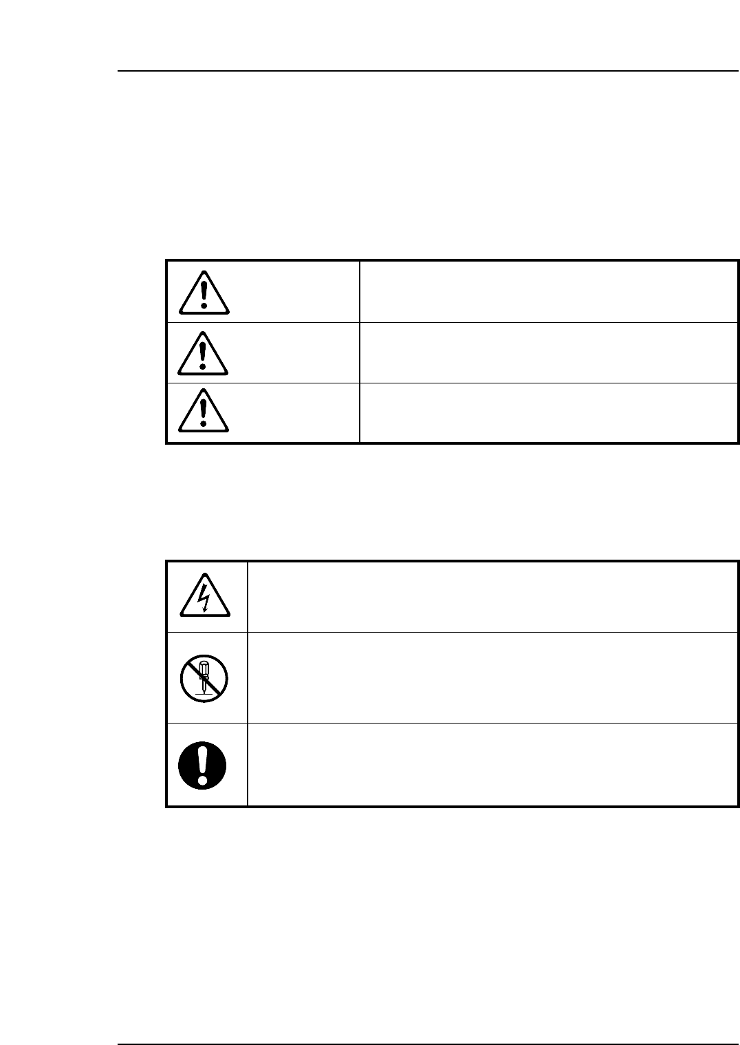
Hazard warnings are divided into the following three classes:
DANGER
The hazard or unsafe practice will cause severe injury or
death.
WARNING
The hazard or unsafe practice may cause severe injury or
death.
CAUTION
The hazard or unsafe practice may lead to personal injury
or damage to the machine.
To distinguish the type of hazard, the following symbols are used in combination with the
ones above.
Hazard Alert
A triangle is used to draw your attention to a hazard. The symbol inside the
triangle indicates the nature of the hazard (in this case electrical shock).
Prohibition
A circle with a diagonal line inside is used to draw your attention to an
operation that is prohibited. The symbol inside the circle indicates the nature
of the operation (in this case disassembly).
A circle with an exclamation mark is used to draw your attention to a
mandatory action. In other words, you are required to carefully carry out the
given instructions.