CP-7[732-742]-series Mechanical Reference(2.9E).pdf - 第132页
3. Open the belt cover. 4. Remove the pulley and the pulley fan, then remove the vacuum pump from the table. Caution: The air filter should not be removed from the vacuum pump for the folllowing reasons. 1. There is a po…
3.8 Replacing the Vacuum Pump Internal Vanes
and Bearings
Point
The vacuum pump blade consists of 6 vanes. Broken vanes can cause abnormal vacuum
pump noise, and may reduce the vacuum force. When replacing the vanes, the bearings
must also be replaced.
Procedure
WARNING
• Be sure to switch off the 200V power supply before
beginning this procedure.
• Do not touch the vacuum pump immediately after
operation as it may be extremely not. Allow the
pump to cool before performing this procedure.
Disassembly
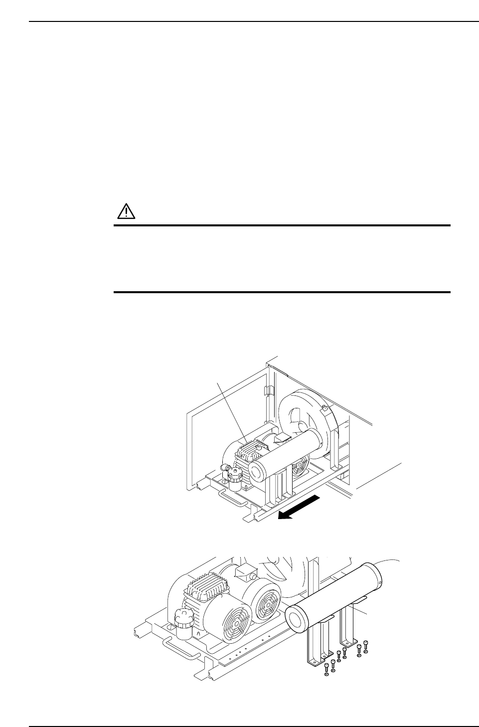
1. Pull out the vacuum pump. (For this procedure, refer to section 3.7 "Replacing the
Vacuum Pump Belt").
2. Remove the duct together with the bracket.
Duct
C7SM3058E
Vacuum pump
C7SM3056E
Part 3 Chapter 3 Replacing Consumable Parts
Edition 2.7 3-3-12 CP-7 series Mechanical Reference
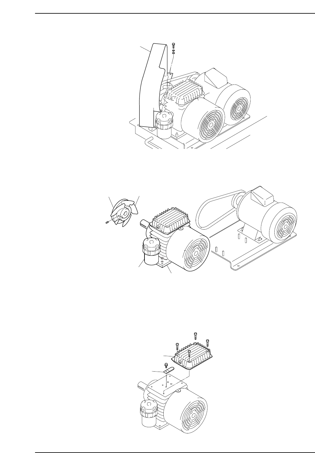
3. Open the belt cover.
4. Remove the pulley and the pulley fan, then remove the vacuum pump from the
table.
Caution: The air filter should not be removed from the vacuum pump for the folllowing
reasons.
1. There is a possibility of damage to the pump plumbing or air filter bousing.
2. Metal fragments or other dust from the plumbing may get into the pump.
5. Remove the silencer case and the check valve.
C7SM3066E
Silencer case
Check valve
Pulley
Pulley fan
Vacuum pump
Air filter
C7SM3065E
Belt cover
C7SM3057E
Part 3 Chapter 3 Replacing Consumable Parts
Edition 2.7 3-3-13 CP-7 series Mechanical Reference
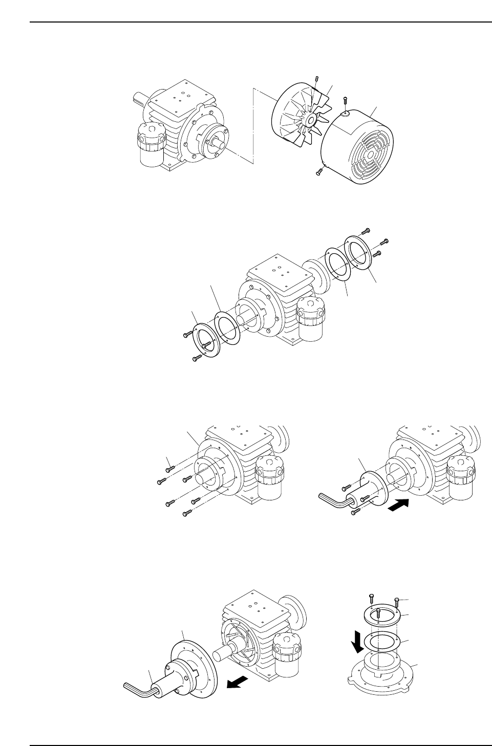
6. Remove the cooling fan cover and the cooling fan.
7. Remove the bearing retainers and liners.
8. Remove the side plate "B" mounting bolts, then use these bolts to secure the special
tool to side plate "B".
9. Pull on the special tool to remove side plate "B".
Remove the special tool from side plate "B", then install the bearing retainer and
liner (removed at step 7 above) on side plate "B". Do not tighten the bolts fully at
this time (back off 1 mm from fully tightened condition).
Note: Use care to avoid scratching side plate "B" and the inner surface of the cylinder.
Side plate B
Special tool
Bearing retainer
Bolt
Liner
C7SM3070E
Side plate
Mounting bolts
C7SM3069E
Side plate B
Special tool
C7SM3068E
Bearing retainer
Bearing retainer
Liner
Liner
C7SM3067E
Fan cover
Cooling fan
Part 3 Chapter 3 Replacing Consumable Parts
Edition 2.7 3-3-14 CP-7 series Mechanical Reference