CP-7[732-742]-series Mechanical Reference(2.9E).pdf - 第134页
10 Remove the vanes. Notes: 1. Be sure to note the orientation and positions of the vanes, as the new vanes must be installed in the same manner. 2. If a broken vane exists, air blow the pump interior to remove any fragm…
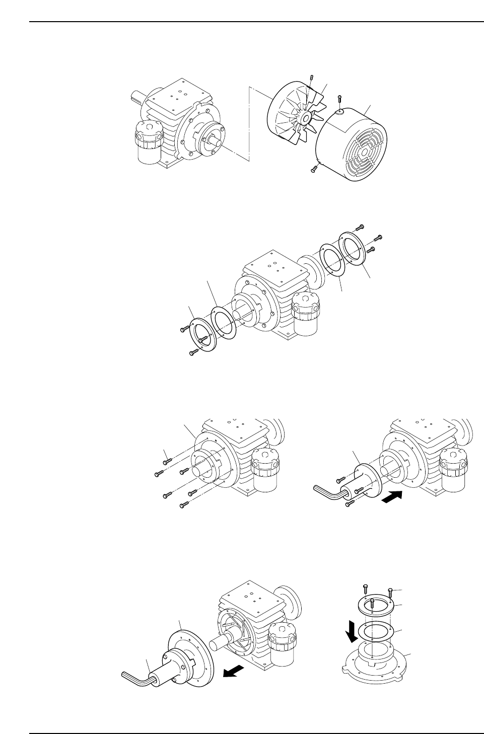
6. Remove the cooling fan cover and the cooling fan.
7. Remove the bearing retainers and liners.
8. Remove the side plate "B" mounting bolts, then use these bolts to secure the special
tool to side plate "B".
9. Pull on the special tool to remove side plate "B".
Remove the special tool from side plate "B", then install the bearing retainer and
liner (removed at step 7 above) on side plate "B". Do not tighten the bolts fully at
this time (back off 1 mm from fully tightened condition).
Note: Use care to avoid scratching side plate "B" and the inner surface of the cylinder.
Side plate B
Special tool
Bearing retainer
Bolt
Liner
C7SM3070E
Side plate
Mounting bolts
C7SM3069E
Side plate B
Special tool
C7SM3068E
Bearing retainer
Bearing retainer
Liner
Liner
C7SM3067E
Fan cover
Cooling fan
Part 3 Chapter 3 Replacing Consumable Parts
Edition 2.7 3-3-14 CP-7 series Mechanical Reference
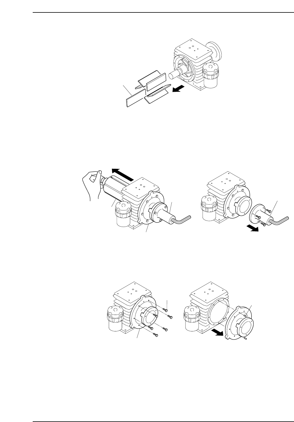
10 Remove the vanes.
Notes:
1. Be sure to note the orientation and positions of the vanes, as the new vanes must be
installed in the same manner.
2. If a broken vane exists, air blow the pump interior to remove any fragments.
11. Mount the special tool on side plate "A", then push out the rotor. Support the
shaft area with your hand to avoid dropping the rotor. After removing the rotor,
remove the special tool.
Note: When pushing out the rotor, use care to avoid scratching the rotor shaft and the
cylinder.
12. Remove the side plate "A" mounting bolts, and use a plastic hammer to knock the
pin off, then remove side plate "A".
13. After disassembling to this point, clean each component using a soft cloth soaked
in an organic solvent (chlorine or fluorine based solvent such as Kurorosen or
Daifuron S3).
Bolt
Knock-pin
C7SM3073E
Side plate A
Special tool
C7SM3072E
Rotor
Side plate A
Special tool
Vane
C7SM3071E
Part 3 Chapter 3 Replacing Consumable Parts
Edition 2.7 3-3-15 CP-7 series Mechanical Reference
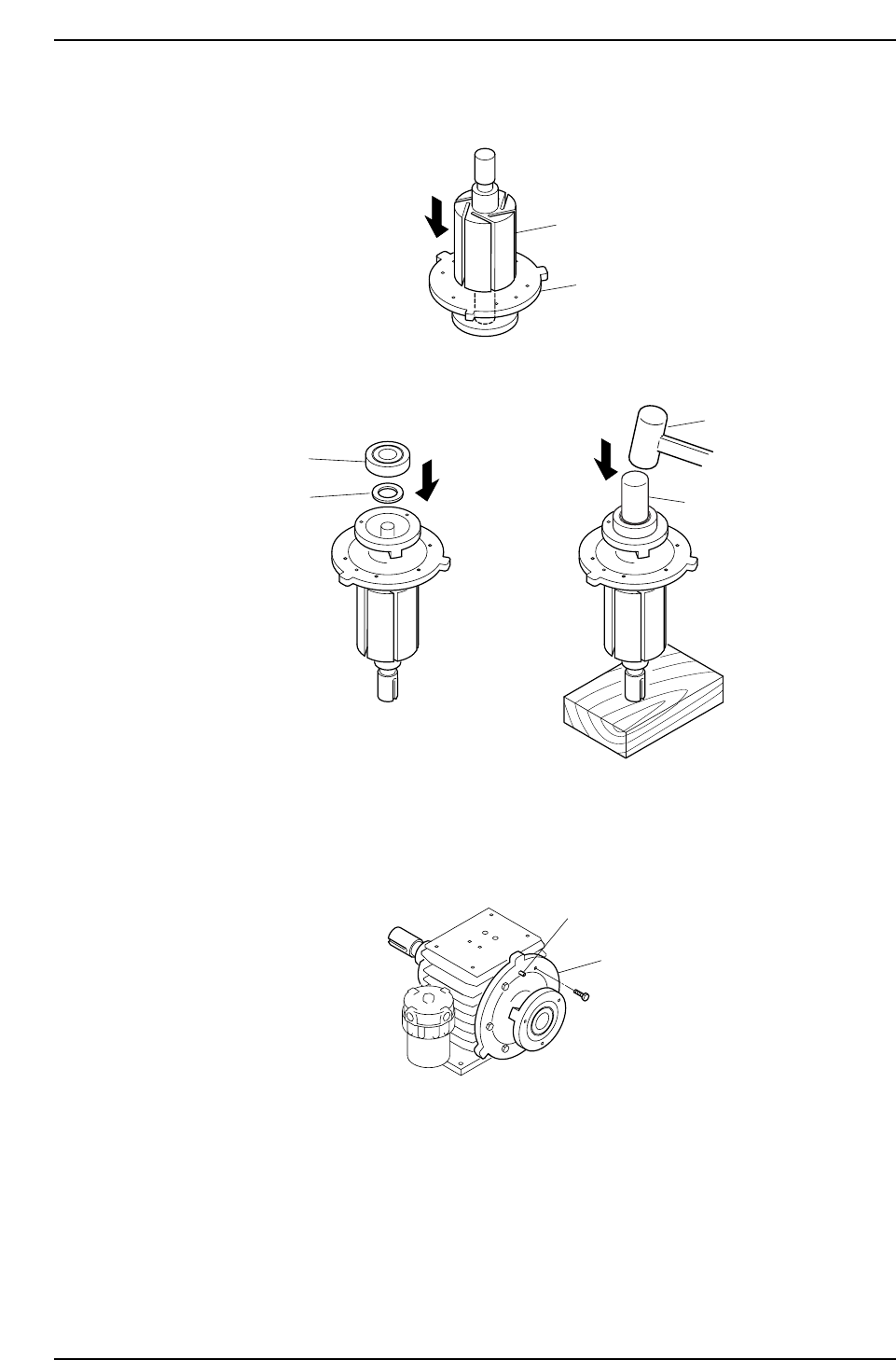
Assembly
1. Insert the rotor into side plate "A".
2. Place the spacer and bearing in side plate "A", then use a bearing punch and
hammer to pound the bearing in.
Note: Place a wood block beneath the shaft to prevent it from being scratched.
3. Mount side plate "A" on the cylinder. After using the knock-pin to position side
plate "A", secure it with the bolts.
Knock-pin
Side plate A
C7SM3076E
Bearing punch
Spacer
Bearing
Hammer
C7SM3075E
Side plate A
Rotor
C7SM3074E
Part 3 Chapter 3 Replacing Consumable Parts
Edition 2.7 3-3-16 CP-7 series Mechanical Reference