CP-7[732-742]-series Mechanical Reference(2.9E).pdf - 第136页
4. Mount the vanes on the rotor. Be sure the vane positions and orientations are the same as when disassembled. 5. Mount side plate "B" on the cylinder. After using the knock-pin to position side plate "B&…
Assembly
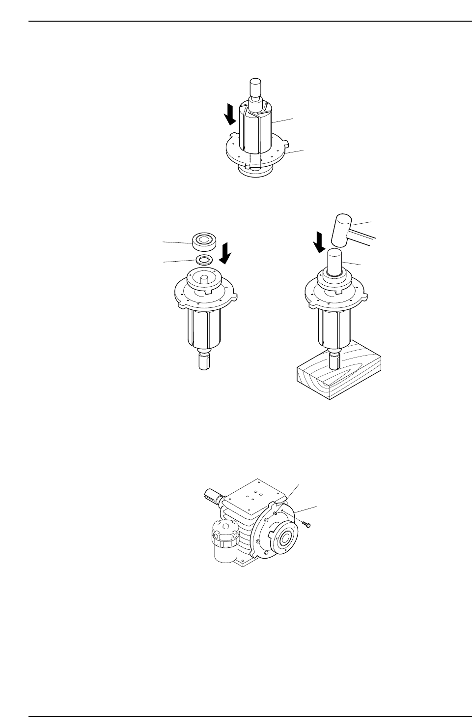
1. Insert the rotor into side plate "A".
2. Place the spacer and bearing in side plate "A", then use a bearing punch and
hammer to pound the bearing in.
Note: Place a wood block beneath the shaft to prevent it from being scratched.
3. Mount side plate "A" on the cylinder. After using the knock-pin to position side
plate "A", secure it with the bolts.
Knock-pin
Side plate A
C7SM3076E
Bearing punch
Spacer
Bearing
Hammer
C7SM3075E
Side plate A
Rotor
C7SM3074E
Part 3 Chapter 3 Replacing Consumable Parts
Edition 2.7 3-3-16 CP-7 series Mechanical Reference
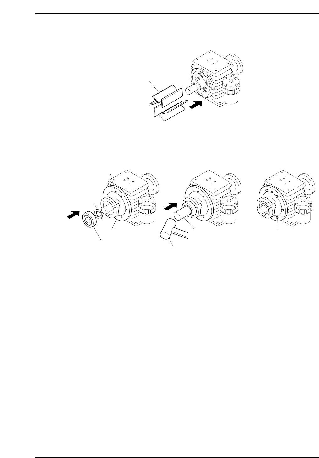
4. Mount the vanes on the rotor. Be sure the vane positions and orientations are the
same as when disassembled.
5. Mount side plate "B" on the cylinder. After using the knock-pin to position side
plate "B", place the spacer and bearing in position, then use a hammer and bearing
punch to pound the bearing in. After the bearing is in, secure the side plate "B"
mounting bolts.
6. Use the bearing punch and hammer again to pound in the bearings at side plates
"A" and "B".
Mounting bolt
Side plate B
Knock-pin
Spacer
Bearing
Bearing punch
Hammer
C7SM3078E
Vane
C7SM3077E
Part 3 Chapter 3 Replacing Consumable Parts
Edition 2.7 3-3-17 CP-7 series Mechanical Reference
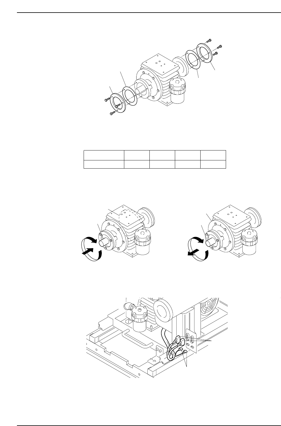
7. Place the liners and bearing retainers on side plates "A" and "B".
Note: Even if the number of liners and their combinations are assembled in the same
manner as when disassembled, there may be some looseness when the shaft
rotates. The number of liners and the liner thickness should therefore be adjusted as
necessary to eliminate this looseness.
8. Verify that there is no contact between the rotor and the side plates when the rotor
is rotated while pushing and pulling the rotor shaft.
9. Complete the vacuum pump reassembly by reversing steps 1 to 6 of the
disassembly procedure, then reconnect the harness connectors.
Conectors
Conectors
C7SM3062E
C7SM3080E
Side plate A
Side plate B
Shaft
Shaft
C7SM3079E
Liner Thickness
Color Coded
0.03 mm
Red
0.05 mm
Yellow
0.10 mm
Black
0.20 mm
No color
C7SM3068E
Bearing retainer
Bearing retainer
Liner
Liner
Part 3 Chapter 3 Replacing Consumable Parts
Edition 2.7 3-3-18 CP-7 series Mechanical Reference