CP-7[732-742]-series Mechanical Reference(2.9E).pdf - 第140页
6. Adjust the tension of the new belt. If the belt tension is outside the prescribed range, move the motor position in 0.1 mm increments to adjust the "L" dimension. 7. Reassemble the remaining parts in the rev…
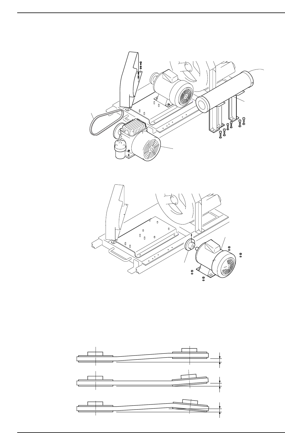
3. Remove all parts which hinder the motor replacement work. These parts include
the vacuum pump, duct, the belt.
4. Remove the motor, then remove the pulley from the motor.
5. Mount the pulley on the new motor, then set the motor and vacuum pump on the
base. Bolts which secure the pulley, motor, and vacuum pump should only be
partially tightened at this time.
Final tightening should be performed after adjusting the pulley deviation and the
distance between the vacuum pump pulley and motor pulley (distance noted at
step 2). The pulley deviation should be 0.3 mm or less.
C7SM3082E
Reference-side pulley
0.3 mm or less
0.3 mm or less
0.3 mm or less
C7SM3061E
Pulley
Motor
C7SM3060E
Duct
Vacuum pump
Belt
Part 3 Chapter 3 Replacing Consumable Parts
Edition 2.7 3-3-20 CP-7 series Mechanical Reference
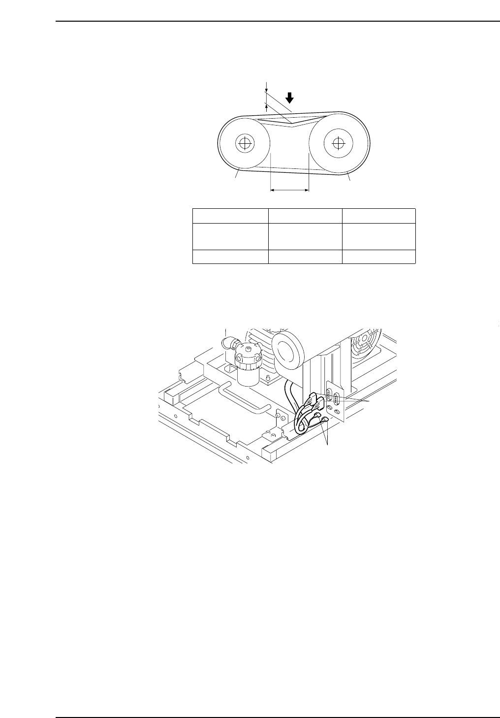
6. Adjust the tension of the new belt. If the belt tension is outside the prescribed
range, move the motor position in 0.1 mm increments to adjust the "L" dimension.
7. Reassemble the remaining parts in the reverse order of the disassembly procedure,
then connect the harness connectors.
Conectors
Conectors
C7SM3062E
C7SM3064E
L
1.8 mm
Motor pulley
Vacuum pump pulley
Load
Amount of slack
Load
Tension meter *
* : Polyflex tension meter manufactured by Gates Co.
New Belt
1.8 mm
0.50 ~ 0.60 kg
28 ~ 34 lb
Belt During Use
1.8 mm
0.38 ~ 0.46 kg
20 ~ 26 lb
Part 3 Chapter 3 Replacing Consumable Parts
Edition 2.7 3-3-21 CP-7 series Mechanical Reference
3.10 Replacing the Vacuum Hoses
Procedure
WARNING
• Be sure to switch off the 200V power supply before
beginning this procedure.
• The spring force may cause the cam axis to rotate if
the cam axis is positioned anywhere other than the
origin position (0 degrees). Always use extreme
care when working inside the machine, as this is a
dangerous area.
1. Detach all nozzle holders.
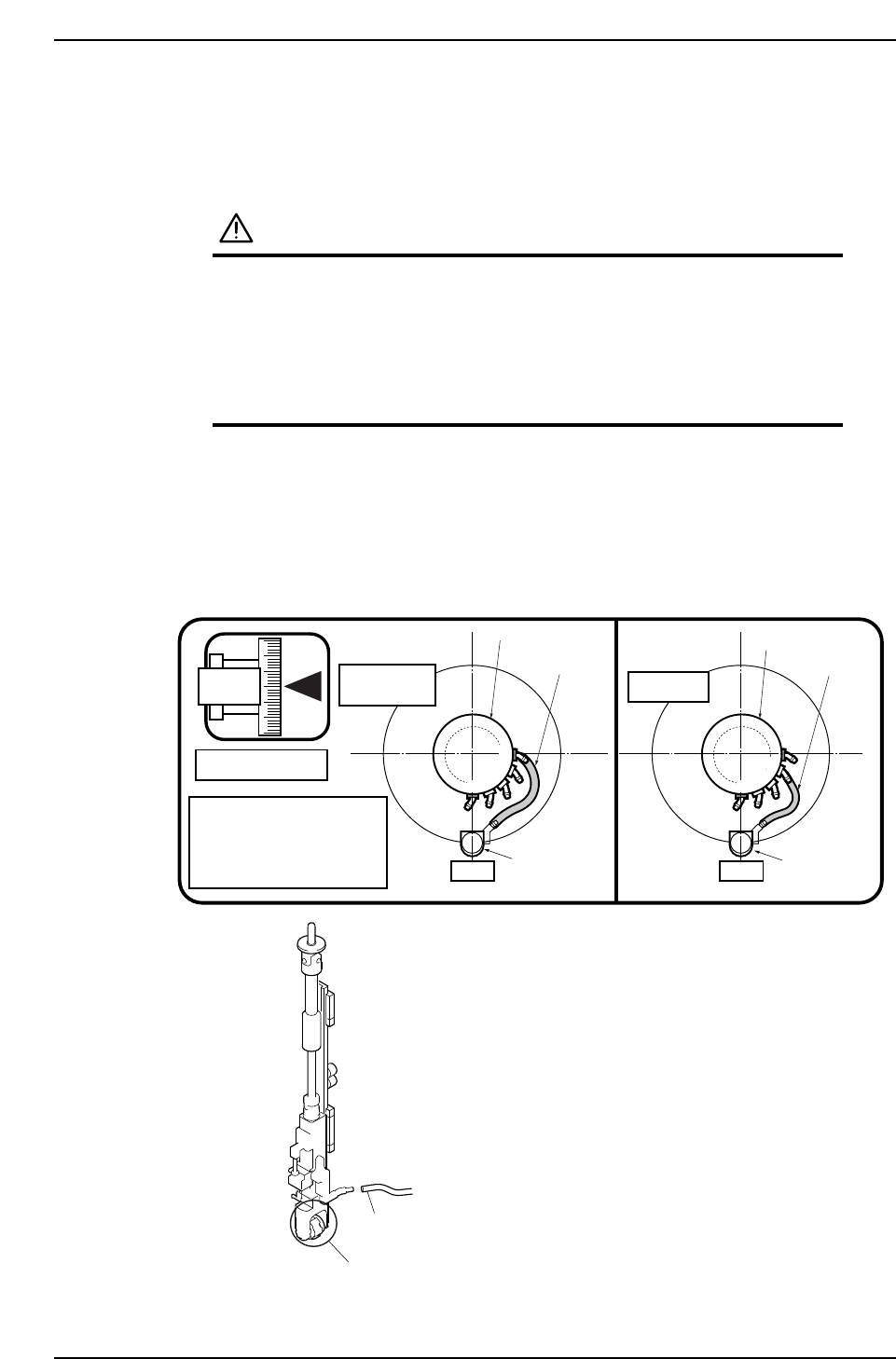
2. Move the placing head where a vacuum hose is to be replaced to ST9, fix the cam
angle at 180 degrees, then replace the vacuum hose between the head manifold
and the nozzle shaft assembly.
3. Connect the vacuum hose to joint 4 for CP-742ME/742E, or joint 3 for CP-732E as
shown in the figure below.
9ST 9ST
CP-742ME
CP-742E
CP-732E
180
Cam angle 180°
Push the hose (from the head
manifold) all the way to the
back of the support axis nipple
at theposition shown in the
figure at right.
Nozzle shaft
assembly
Nozzle shaft
assembly
Vacuum hoses
Vacuum hoses
Head manifold
Head manifold
1
0
1
0
2
3
4
3
2
Vacuum hoses
Nozzle holder
C7SM3083E
Part 3 Chapter 3 Replacing Consumable Parts
Edition 2.7 3-3-22 CP-7 series Mechanical Reference