CP-7[732-742]-series Mechanical Reference(2.9E).pdf - 第142页
3.1 1 Replacing the UV Lamp The UV lamp installation procedure differs depending on machine type and X-No. Confirm the machine X-No. and installation procedure prior to replacing the UV lamp. The installation procedure f…
3.10 Replacing the Vacuum Hoses
Procedure
WARNING
• Be sure to switch off the 200V power supply before
beginning this procedure.
• The spring force may cause the cam axis to rotate if
the cam axis is positioned anywhere other than the
origin position (0 degrees). Always use extreme
care when working inside the machine, as this is a
dangerous area.
1. Detach all nozzle holders.
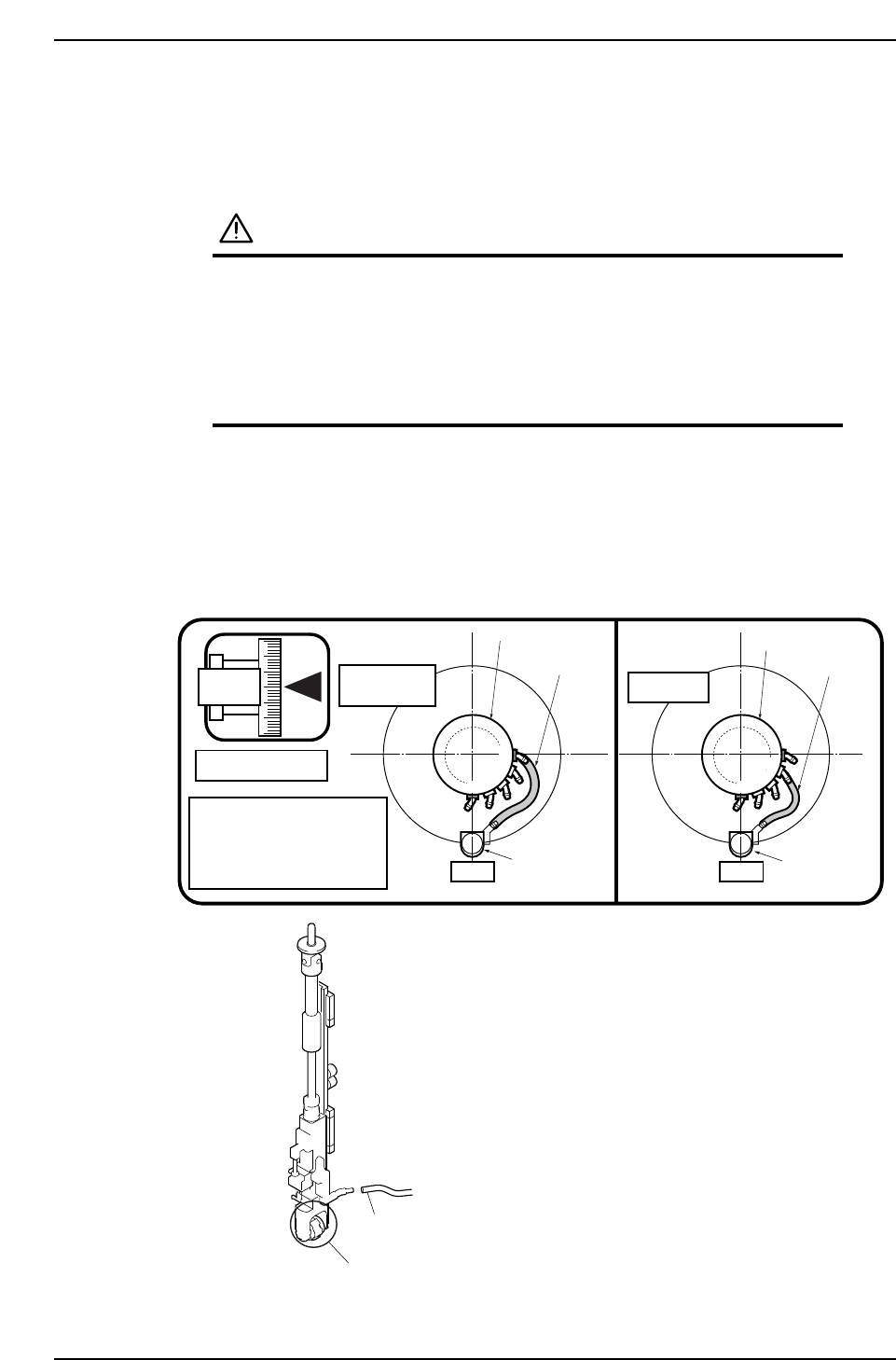
2. Move the placing head where a vacuum hose is to be replaced to ST9, fix the cam
angle at 180 degrees, then replace the vacuum hose between the head manifold
and the nozzle shaft assembly.
3. Connect the vacuum hose to joint 4 for CP-742ME/742E, or joint 3 for CP-732E as
shown in the figure below.
9ST 9ST
CP-742ME
CP-742E
CP-732E
180
Cam angle 180°
Push the hose (from the head
manifold) all the way to the
back of the support axis nipple
at theposition shown in the
figure at right.
Nozzle shaft
assembly
Nozzle shaft
assembly
Vacuum hoses
Vacuum hoses
Head manifold
Head manifold
1
0
1
0
2
3
4
3
2
Vacuum hoses
Nozzle holder
C7SM3083E
Part 3 Chapter 3 Replacing Consumable Parts
Edition 2.7 3-3-22 CP-7 series Mechanical Reference
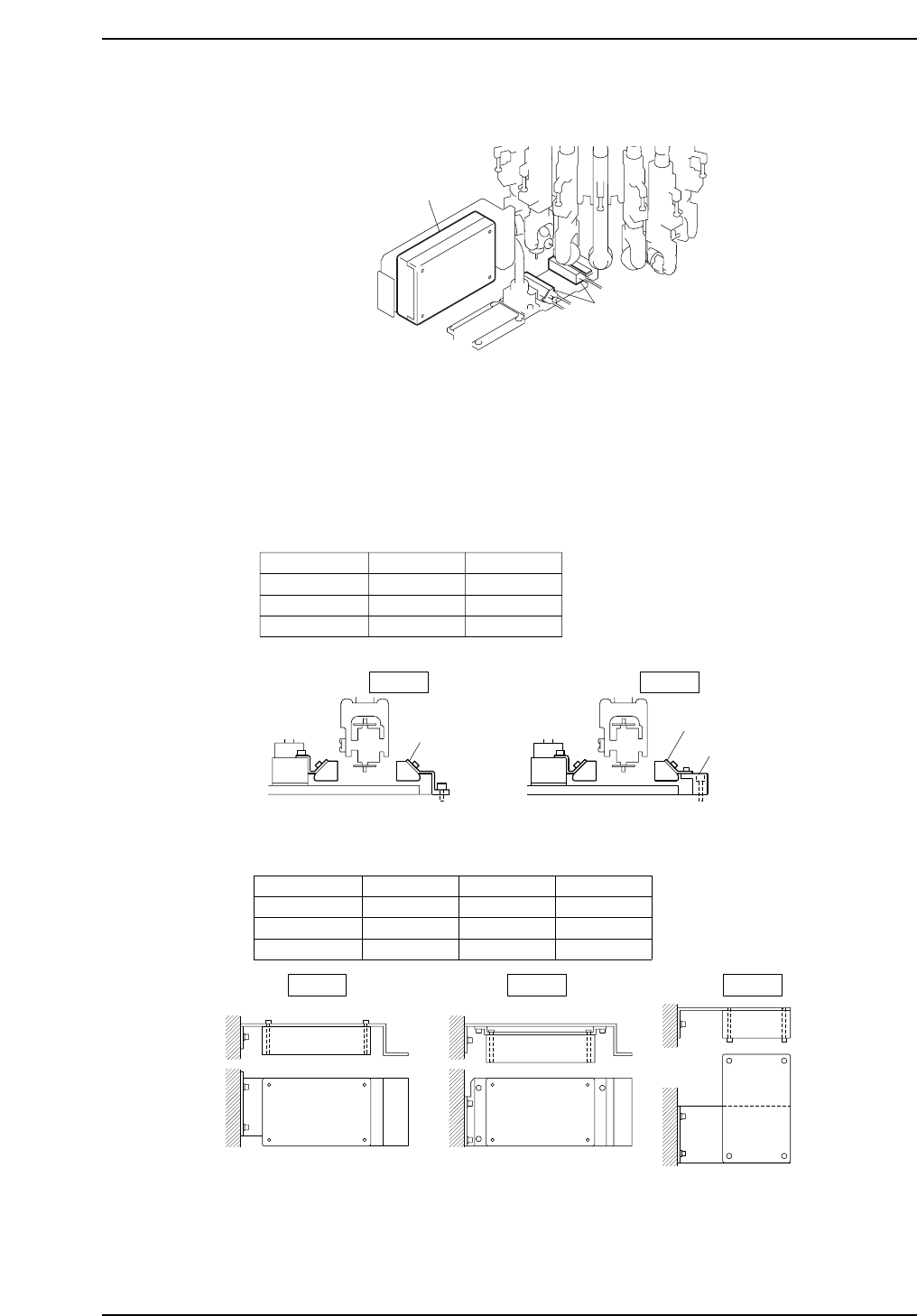
3.11 Replacing the UV Lamp
The UV lamp installation procedure differs depending on machine type and X-No.
Confirm the machine X-No. and installation procedure prior to replacing the UV lamp.
The installation procedure for the power supply unit, which is also removed when
replacing the UV lamp, also differs depending on the machine.
UV Lamp and Lamp Bracket
Power Supply Unit and Mounting Bracket
C7SM3086E
Type 1 Type 2 Type 3
CP-732E
CP-742E
CP-742ME
~CX29
-
-
CX29~CX49
Type 1 Type 2 Type 3
-
-
CX49~
CX4~
CX7~
C7SM3085E
CP-732E
CP-742E
CP-742ME
~CX155
-
~CX99
CX156~
Type A Type B
Type A Type B
CX4~
CX100~
A2835DCGC6023
DCGC0140
DCGC0261
C7SM3090E
UV lamp
Power supply unit
Part 3 Chapter 3 Replacing Consumable Parts
Edition 2.7 3-3-23 CP-7 series Mechanical Reference
Note) The machine X-No. is indicated on the sticker on the out conveyor.
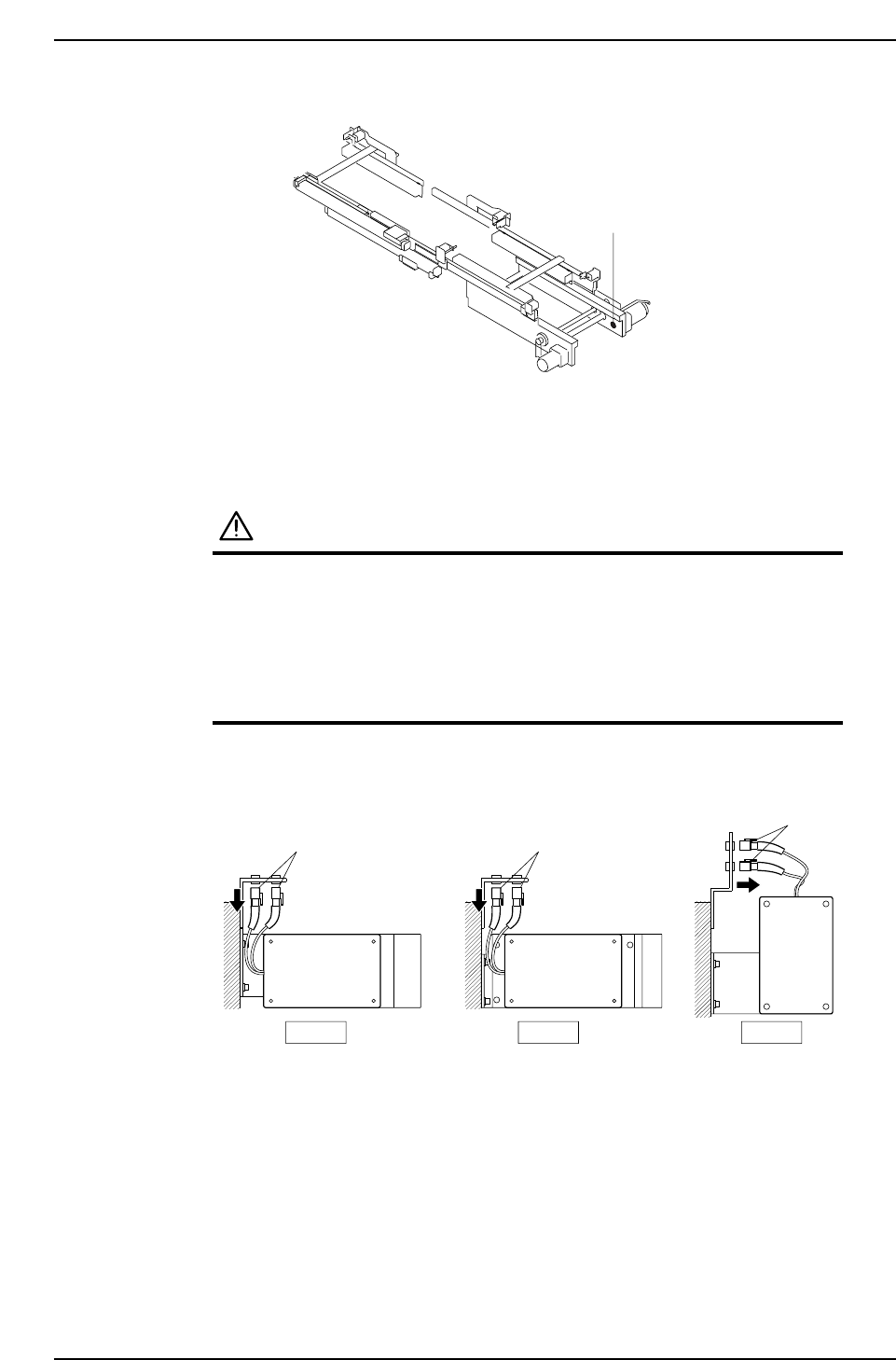
Procedure
WARNING
• Be sure to switch off the 200V power supply before
beginning this procedure.
• The spring force may cause the cam axis to rotate if
the cam axis is positioned anywhere other than the
origin position (0 degrees). Always use extreme
care when working inside the machine, as this is a
dangerous area.
1. Disconnect the connectors of the power supply unit.
C7SM3091E
Type 1 Type 2 Type 3
Connector
ConnectorConnector
C7SM3087E
Sticker
Part 3 Chapter 3 Replacing Consumable Parts
Edition 2.7 3-3-24 CP-7 series Mechanical Reference