CP-7[732-742]-series Mechanical Reference(2.9E).pdf - 第153页
1.1.2 Advance Sensor Position Adjustment 1. When the dog is at the lower limit at cam angle 200°, ensure that the sensor is ON. 2. Set a dial gauge to the roller and adjust the sensor to go off 0.5 mm above the lower lim…
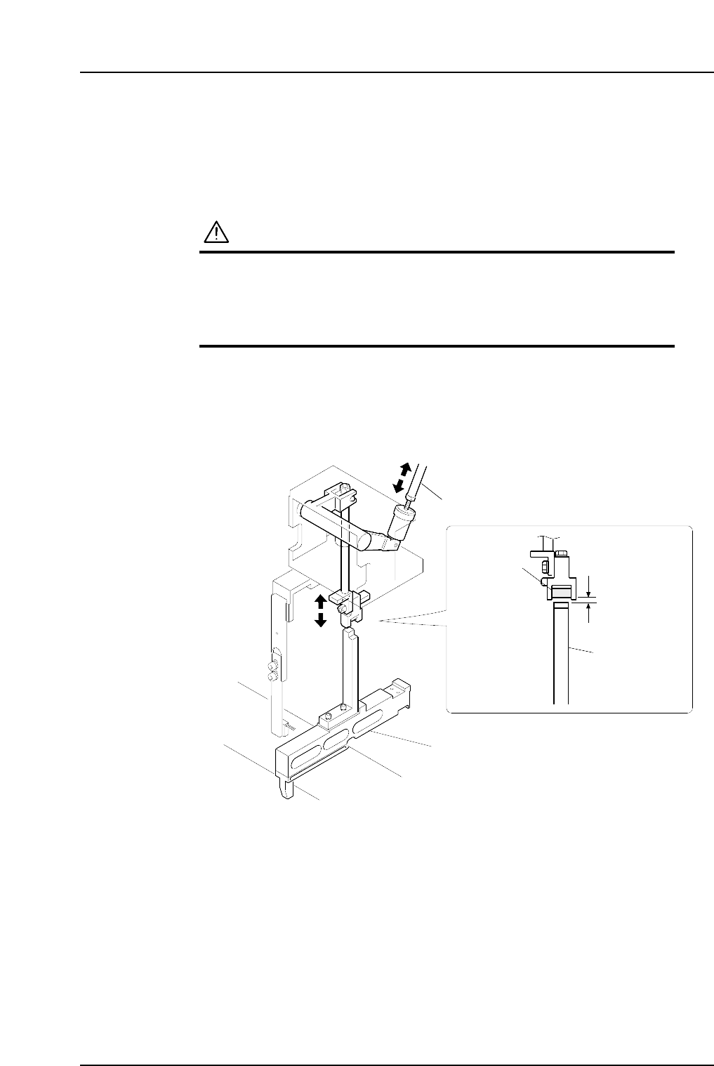
1.1.1 Rod Adjustment
1. Set the positioning jig (ADCPJ8020) in the D1 position.
2. Press [Position] - (Position) [D1-axis] - enter [1] - [OK] and the START button to
move the positioning jig to station 1.
3. Press the EMERGENCY STOP button to take the 200V down to 100V.
WARNING
• Always be sure to cut off the 200V power before carrying
out any work.
• Exercise extreme caution when working on the machine if
the cam is not at its origin (0 deg.). Recoil of the cam
axis can endanger the operator.
4. Use the cam handle to rotate the cam to 0°.
5. Switch the I/O (TAPE FEED SOL ON) setting ON.
6. Adjust the rod so that there is 0.5 mm clearance between the top of the positioning
jig and the roller.
Adjustment rod
Roller
C73M4001b
0.5 mm
Positioning jig
(ADCPJ8020)
Positioning jig (ADCPJ8020)
Part 4 Chapter 1 Station Adjustments
Edition 2.4 4-1-2 CP-7 series Mechanical Reference
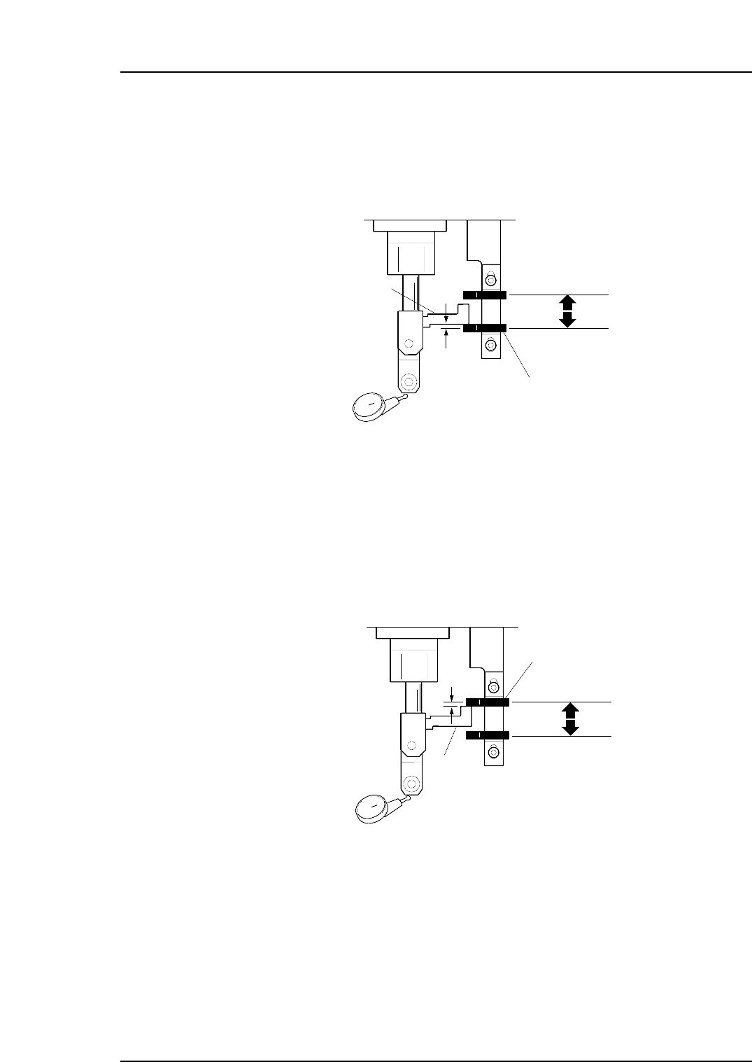
1.1.2 Advance Sensor Position Adjustment
1. When the dog is at the lower limit at cam angle 200°, ensure that the sensor is ON.
2. Set a dial gauge to the roller and adjust the sensor to go off 0.5 mm above the
lower limit.
1.1.3 Retract Sensor Position Adjustment
1. When the dog is at the upper limit at cam angle 0°, ensure that the sensor is ON.
2. Set a dial gauge to the roller and adjust the sensor to go off 0.5 mm below the
upper limit.
Retract sensor
Dog Lower Limit
0.5 mm
Dog Upper Limit
Dog
C7SM4004a
Advance sensor
Dog Lower Limit
Dog Upper Limit
Dog
C7SM4003a
0.5 mm
Part 4 Chapter 1 Station Adjustments
Edition 2.4 4-1-3 CP-7 series Mechanical Reference
1.2 Tape-end Detection (Station 1)
Point
Tape end detection is performed by a reflector type sensor which activates at a point near
the end of the tape. This enables the operator to know when a feeder is nearly out of
tape.
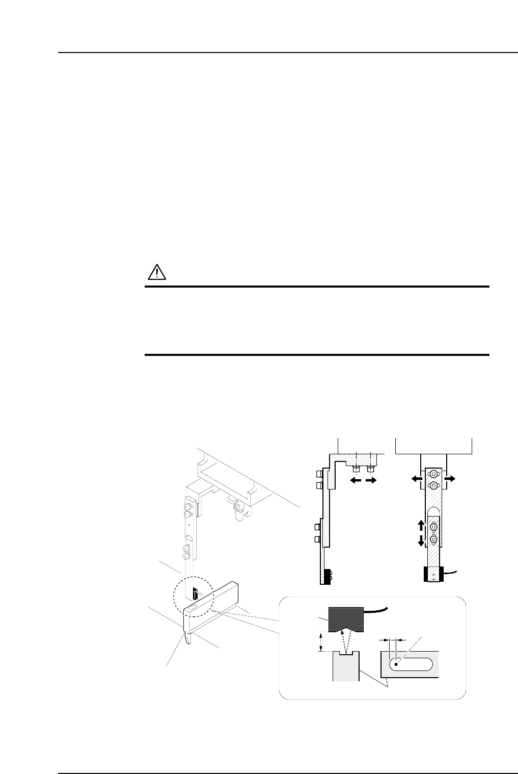
1.2.1 Sensor Position Adjustment
1. Set the adjustment jig (Z9526ADCPJ8550) in the D1 position.
2. Press [Position] - (Position)[D1-axis] - enter[1] - [OK] and the START button to
move the adjustment jig to station 1.
3. Press the EMERGENCY STOP button to take the 200V down to 100V.
WARNING
• Always be sure to cut off the 200V power before carrying
out any work.
• Exercise extreme caution when working on the machine if
the cam is not at its origin (0 deg.). Recoil of the cam
axis can endanger the operator.
4. Ensure that the distance between the top surface of the adjustment jig and the
sensor is approximately 11 to 12 mm.
5. Adjust the sensor position so that the sensor beam appears at 7 mm from the rear
edge of the adjustment jig slit.
Sensor
11
~
12 mm
7 mm
Beam
Adjustment jig
(Z9526ADCPJ8550)
Adjustment jig
C7SM4005b
Part 4 Chapter 1 Station Adjustments
Edition 2.4 4-1-4 CP-7 series Mechanical Reference