CP-7[732-742]-series Mechanical Reference(2.9E).pdf - 第158页
Part 4 Chapter 1 Station Adjustments Edition 2.4 4-1-8 CP-7 series Mechanical Reference 1.4 Nozzle V ertical Movement During Pickup (Station 1) 1.4.1 Slider Adjustment Adjust the height of the slider to ensure that the c…
Part 4 Chapter 1 Station Adjustments
Edition 2.4 4-1-7 CP-7 series Mechanical Reference
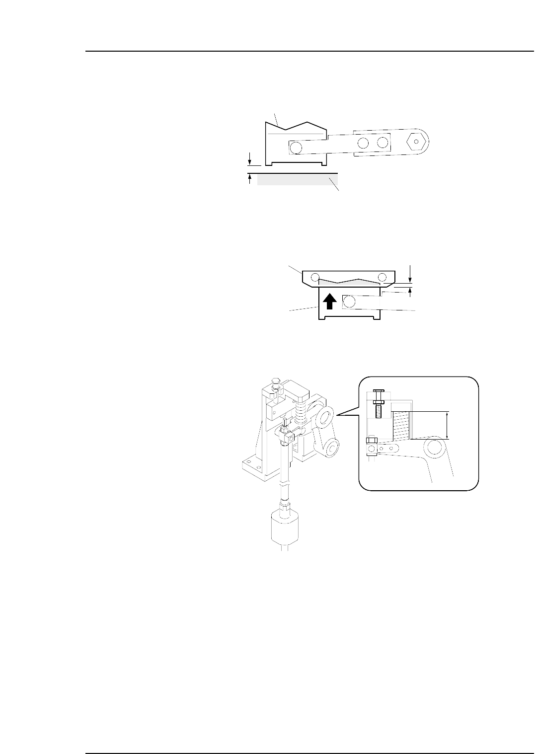
3. Ensure that there is a gap of 0 ~ 0.5 mm between the movable cutter lower surface
and the cutter unit base.
4. Use the cam handle to rotate the cam to 194°.
5. Adjust the rod so that the movable blade and fixed blade engages by 0.5 to 1.0
mm.
6. Ensure that the spring length is 38 mm.
C7SM4010b
38 mm
Fixed cutter
Movable cutter
0.5~1.0 mm
C7SM4008a
0~0.5 mm
C7SM4009b
Movable cutter
Cutter plate
Part 4 Chapter 1 Station Adjustments
Edition 2.4 4-1-8 CP-7 series Mechanical Reference
1.4 Nozzle Vertical Movement During Pickup
(Station 1)
1.4.1 Slider Adjustment
Adjust the height of the slider to ensure that the cam follower can travel smoothly
through the slider and along the cam groove.
1. Press the EMERGENCY STOP button to take the 200V down to 100V.
WARNING
• Always be sure to cut off the 200V power before carrying
out any work.
• Exercise extreme caution when working on the machine if
the cam is not at its origin (0 deg.). Recoil of the cam
axis can endanger the operator.
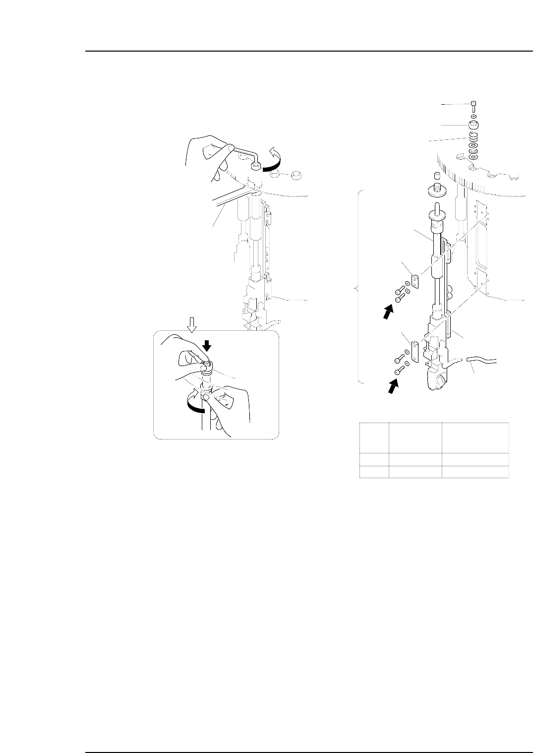
2. In order to remove the nozzle shaft assembly, it is first necessary to remove the
upper clutch. Set the cam angle to zero degrees and use a spanner (DCPJ0450) to
loosen the bolt on the nozzle shaft moving from station 9 to station 10. Turn the
loosened bolt by hand and then remove the clutch. (see next page illustration)
Caution: Remove the nozzle shaft assembly which bears either a “G” or “O” identifier
seal. Operations may be complicated if other nozzle shaft assemblies are
removed.
3. Remove the linear guide clampers and vacuum hose, then remove the nozzle shaft
assembly.
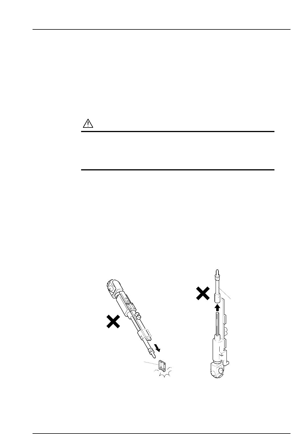
Caution: When handling the nozzle shaft assembly exercise caution to ensure that the
linear guide and outer shaft do not become separated.
Outer shaft
C7SM4011a
Linear guide
Part 4 Chapter 1 Station Adjustments
Edition 2.4 4-1-9 CP-7 series Mechanical Reference
Caution: Do not disassemble the placing head assembly carelessly. Special equipment and
skills are required to perform the reassembly of the placing head. Such procedures
should be attempted only by users who have attended training at Fuji and are
equipped with the necessary tools, or whilst under the direct guidance of a
serviceman.
Outer
shaft
Clamper
Spanner
( DCPJ0450 )
Clutch
Bolt
Spring
Linear guide
Vaccum hose
A
B
Part
Bolt
size
Torque
Nm ( Kgf•cm )
A
B
M4
M4
2 ( 20 )
2 ( 20 )
Clamper
C7SM4012a
Nozzle
shaft
assembly
Caution : Washers may jump when the
bolt is loosened because of the
spring under the clutch.
Rotate the placing
head while holding
the bolt with your
finger.