CP-7[732-742]-series Mechanical Reference(2.9E).pdf - 第160页
Part 4 Chapter 1 Station Adjustments Edition 2.4 4-1-10 CP-7 series Mechanical Reference 4. Move the area for the removed placing head to station 1, then turn on the solenoid Y031 ST1 PICKUP SOL ENGAGED. 5. Set the cam a…
Part 4 Chapter 1 Station Adjustments
Edition 2.4 4-1-9 CP-7 series Mechanical Reference
Caution: Do not disassemble the placing head assembly carelessly. Special equipment and
skills are required to perform the reassembly of the placing head. Such procedures
should be attempted only by users who have attended training at Fuji and are
equipped with the necessary tools, or whilst under the direct guidance of a
serviceman.
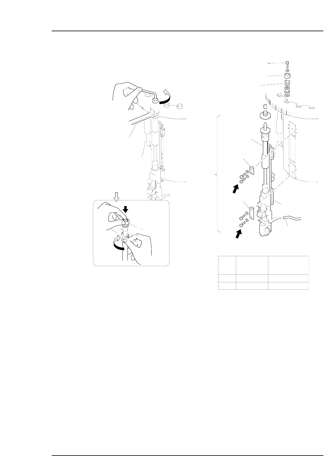
Outer
shaft
Clamper
Spanner
( DCPJ0450 )
Clutch
Bolt
Spring
Linear guide
Vaccum hose
A
B
Part
Bolt
size
Torque
Nm ( Kgf•cm )
A
B
M4
M4
2 ( 20 )
2 ( 20 )
Clamper
C7SM4012a
Nozzle
shaft
assembly
Caution : Washers may jump when the
bolt is loosened because of the
spring under the clutch.
Rotate the placing
head while holding
the bolt with your
finger.
Part 4 Chapter 1 Station Adjustments
Edition 2.4 4-1-10 CP-7 series Mechanical Reference
4. Move the area for the removed placing head to station 1, then turn on the solenoid
Y031 ST1 PICKUP SOL ENGAGED.
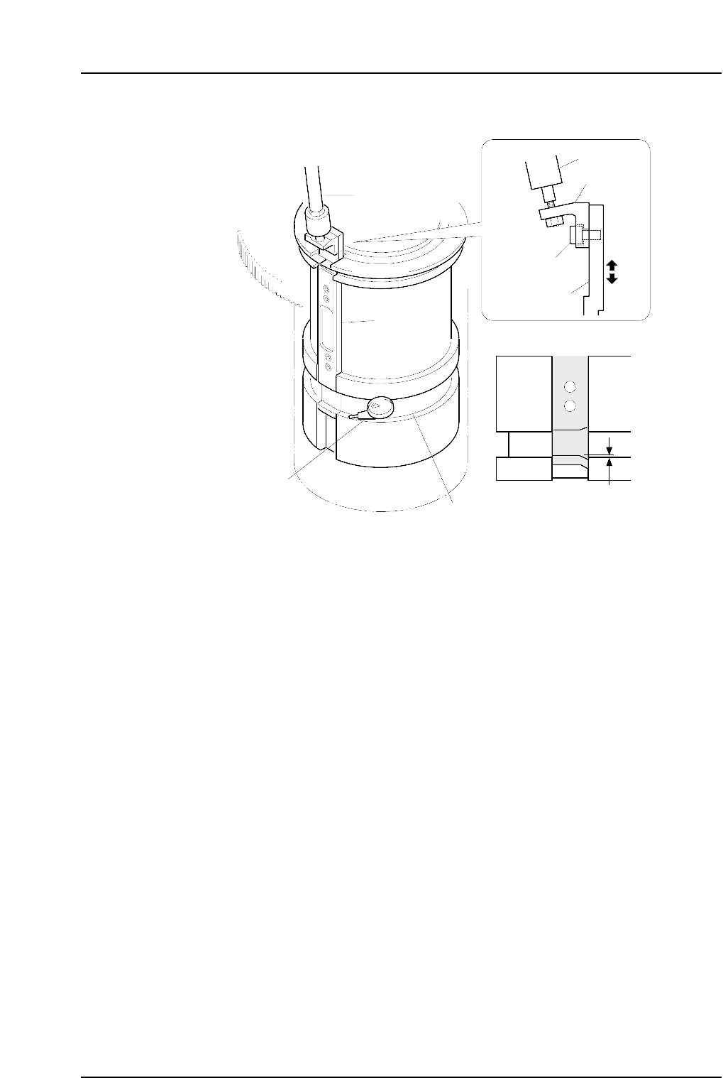
5. Set the cam angle to 0°, and position the dial gauge as shown in the figure above.
6. Check that the distance between the cam channel on the slider and the fixed cam
channel is 0 to 0.02 mm. If this range is exceeded, loosen the bolt on the rod
bracket and make the required adjustments to the height of the slider.
7. Tighten the bolt whilst maintaining the height of the slider.
8. Check the distance between the cam channels again.
Note: If the distance between the channels still does not fall within the range then it may be
necessary to adjust the unit that controls the vertical movement of the nozzle.
9. Reattach the placing head assembly in the original location. Use the clutch
alignment jig and reverse the removal procedures to attach the placing head.
Slider
Rod
0~0.02 mm
C7SM4013b
Dial gauge
Rod
Bracket
Bolt
Slider
Cam groove
Part 4 Chapter 1 Station Adjustments
Edition 2.4 4-1-11 CP-7 series Mechanical Reference
1.4.2 Confirming the Pick-up Height
Ensure that the nozzle descends low enough to pick up a part set in the feeder. Confirm
that the mechanical valve movement creates a vacuum for part pick-up.
1. Set a W8xP4 mm feeder (with tape leaf removed) at the D1 position.
2. Move the feeder to station 1 by pressing [Position] - (Position) [D1-axis] - enter [1]
- [OK] - START.
3. Check that the NZ-axis is stopping at the position specified at the "PICK UP POS.
NZ" item in Proper data.
WARNING
Exercise extreme caution when working on the machine if
the cam is not at its origin (0 deg.). Recoil of the cam axis
can endanger the operator.
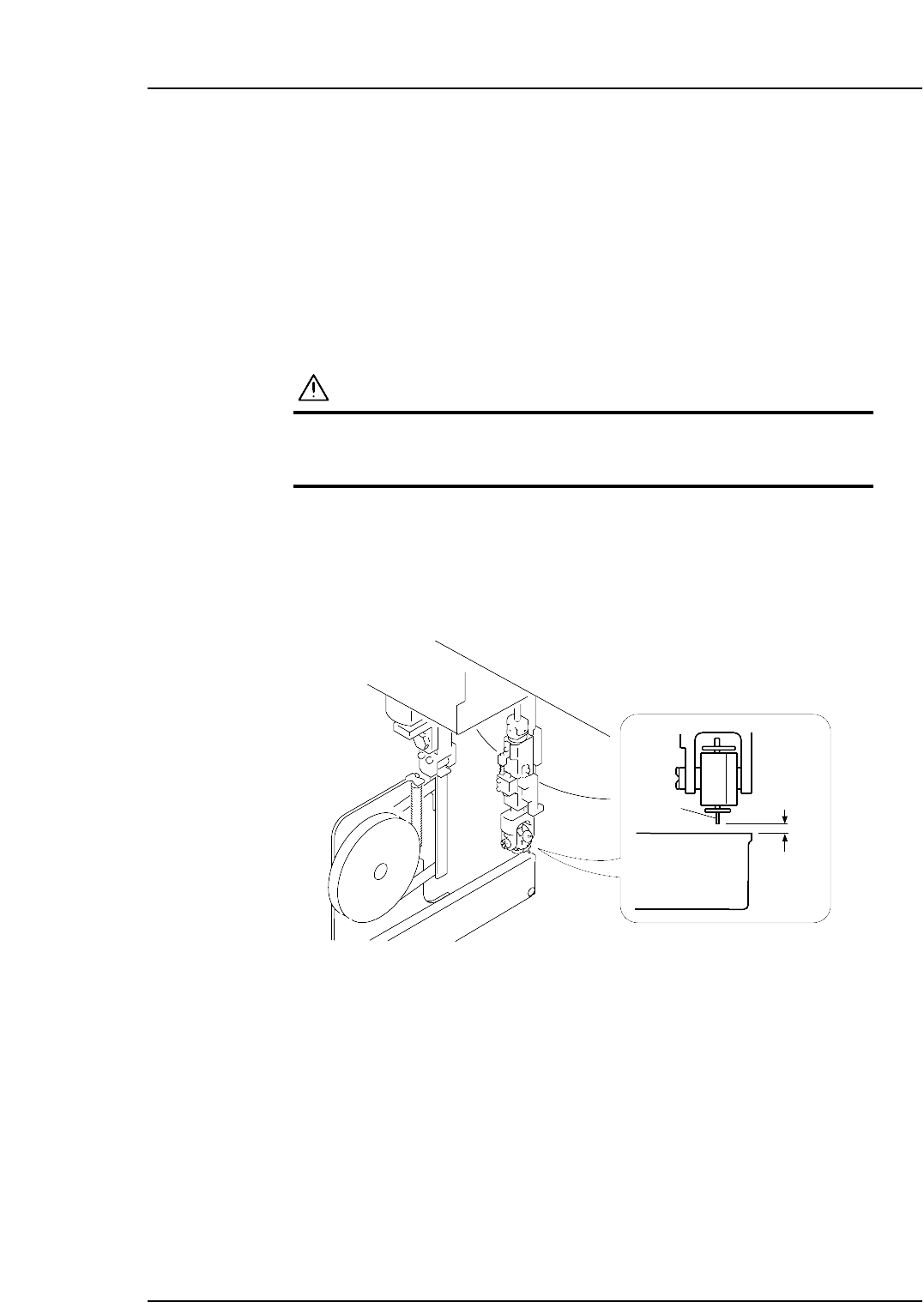
4. Set the cam angle to 0 degrees, then turn the first nozzle solenoid valve on to work
the cam lever.
5. Use the inching keys to rotate the cam to 170°.
6. Use a thickness gauge to ensure a space of 0.65 mm between the tip of the nozzle
and the feeder (pick-up height).
0.65 mm
Feeder
Nozzle
C7SM4014