CP-7[732-742]-series Mechanical Reference(2.9E).pdf - 第167页
1.6 Feeder Height Error Detection (Station 1) Point To detect the positions of the feeders, two sets of sensors are used at each of the retract areas. A further pair of sensors are also used at the pickup position, bring…
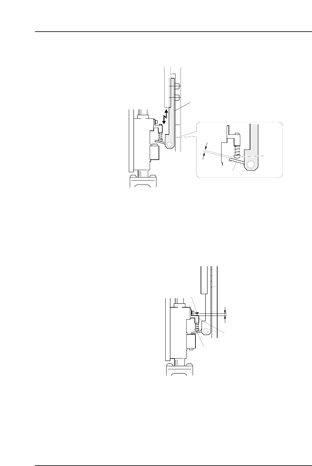
4. Adjust the height of the bracket so that the distance between the lever and the pin
is 0.6 mm.
5. Return the cam angle to 0 degrees. Switch on the 1st nozzle UP/DOWN solenoid
valve in order to work the cam lever.
Check the servo counter to verify that the Proper data (PICK UP POS. NZ) is at the
pick-up height (approx. 4000 pulse position).
6. Use the cam handle to rotate the cam to 170 degrees.
7. Ensure that the clearance of the pin from the bracket is within the range of 0.5 to
1.0 mm after the pin has been raised by the lever.
0.5~1.0 mm
Pin bracket
Pin
Lever
C7SM4021a
Lever bracket
C7SM4020a
0.6 mm
Lever
Pin
Part 4 Chapter 1 Station Adjustments
Edition 2.4 4-1-16 CP-7 series Mechanical Reference
1.6 Feeder Height Error Detection (Station 1)
Point
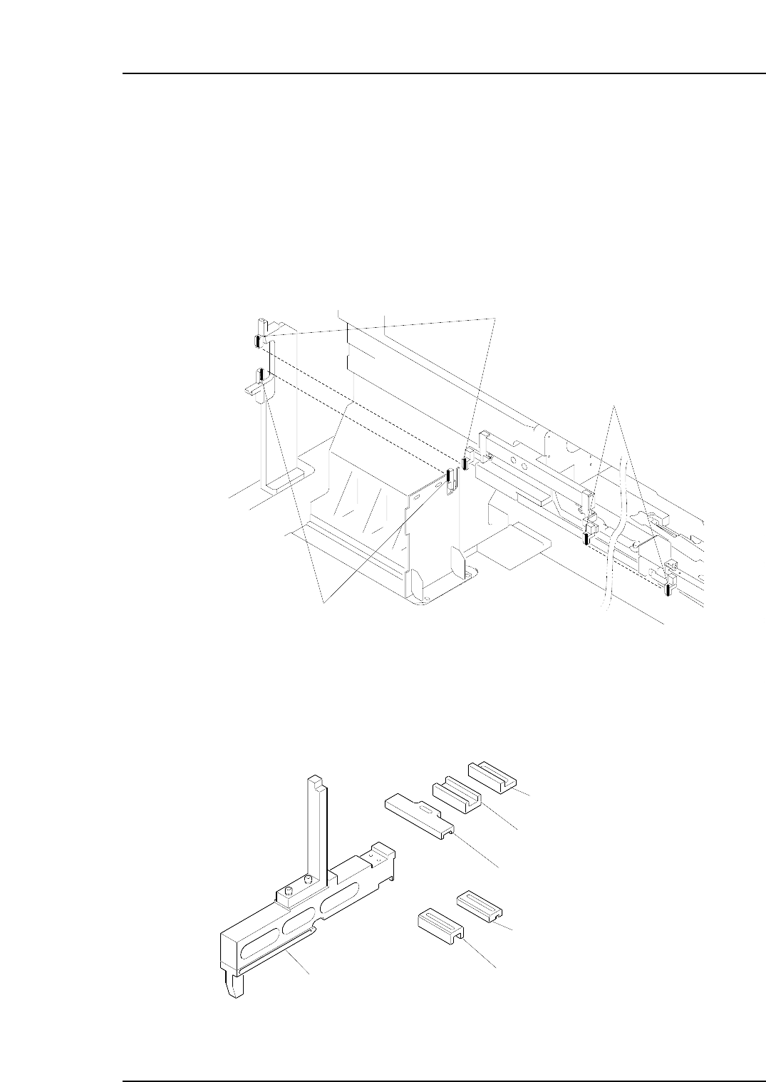
To detect the positions of the feeders, two sets of sensors are used at each of the retract
areas. A further pair of sensors are also used at the pickup position, bringing the total
number to five.
A dedicated jig is used to position these sensors. The sensitivity of the sensors must also
be adjusted.
Note: The above figure represents device table one, but the same arrangement can also be found
on device table two.
The jig used to adjust the sensor positions is shown below.
Positioning jig body
(ADCPJ8020)
Block
(DCPJ0040)
Block
(DCPJ0050) < For CP-732E/CP-742ME >
Block
(DCPJ0060)
Block
(DCPJ0070)
Block
(DGPJ5070) < For CP-742E >
C7SM4049b
Feeder check sensor
(D1 retract area upper direction check)
Feeder check sensor
(D1 retract area lower direction check)
Feeder check sensor
(Pickup area upper direction check)
C7SM4022a
Part 4 Chapter 1 Station Adjustments
Edition 2.4 4-1-17 CP-7 series Mechanical Reference
1.6.1 Feeder Check Sensor Position Adjustment
1. Press the EMERGENCY STOP button to turn off the 200V power, leaving only the
100V power on.
WARNING
Always be sure to cut off the 200V power before carrying
out any work.
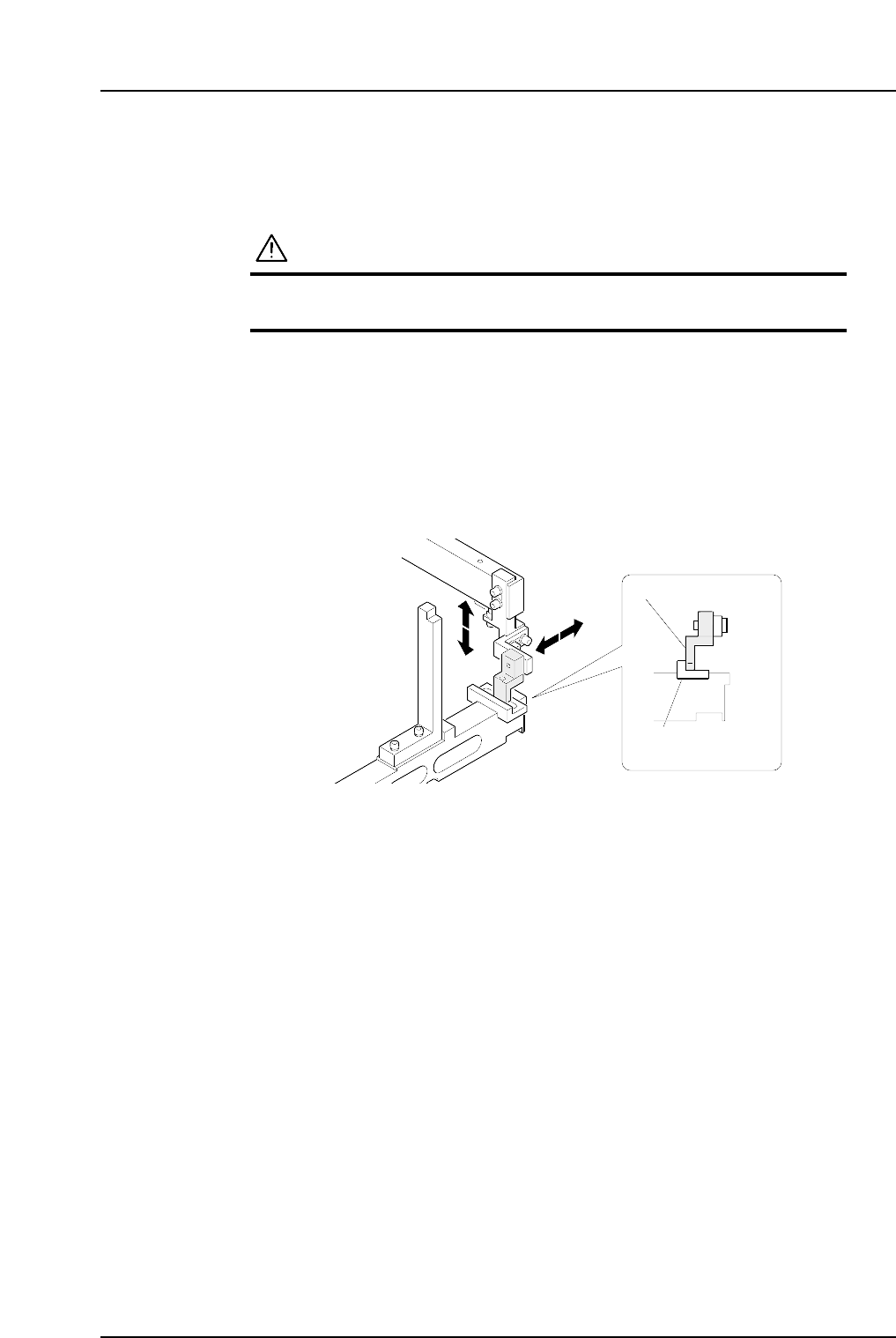
2. Set the positioning jig body on a feeder pallet.
3. Use the inching keys to position the feeder pallet and bring the positioning jig
body within the vicinity of the sensor in question.
4. Attach a block appropriate for each sensor within the jig and then adjust the
sensor position.
Pick-up Area
Block
(DCPJ0040)
Sensor bracket
C7SM4050a
Part 4 Chapter 1 Station Adjustments
Edition 2.4 4-1-18 CP-7 series Mechanical Reference