CP-7[732-742]-series Mechanical Reference(2.9E).pdf - 第183页
5. Place a dial gauge on the top end of the cam lever and set the gauge reading to “0”. In this condition, the cam axis will be at its 180-degree position, and the nozzle UP/DOWN rod will be at its DOWN limit position. V…
1.10.3 Adjusting the Nozzle DOWN Limit Sensors
The nozzle DOWN limit sensor which detects the down limit position of the nozzle
UP/DOWN rod is mounted inside the cam box. Adjust the mounting position of this
sensor so that it switches ON when the nozzle is at its DOWN limit position.
Note: When performing the DOWN limit sensor adjustment after the UP limit sensor adjustment,
remove the dial gauge from the machine to avoid interference between the dial gauge and
the cam lever.
1. Press the EMERGENCY STOP button to take 200V down to 100V.
WARNING
• Always be sure to cut off the 200V power before carrying
out any work.
• Exercise extreme caution when working on the machine if
the cam is not at its origin (0 deg.). Recoil of the cam
axis can endanger the operator.
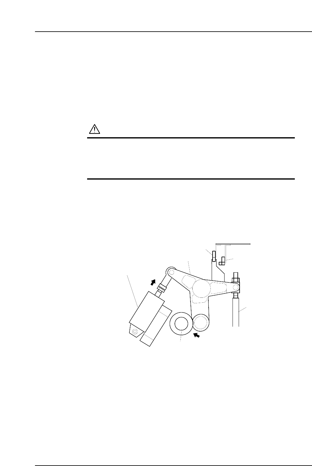
2. Set the cam axis at the 0-degree position.
3. Activate the ST 9 placing solenoid air cylinder (located in the cam box):
Execute the following I/O commands: [Maintenance] - [I/O Check] - [Standard I/O]
- [Y035 ST9 PLACE SOL ENGAGED] - [Output Signal ON]
The cam lever will then follow the cam axis.
4. Use the cam handle to rotate the cam to 180°.
9ST Place solenoid
air cylinder
Cam lever
Nozzle UP/DOWN rod
Cam axis
Cam lever follows
the cam axis.
C7SM4029a
Nozzle up limit sensor
Nozzle down limit sensor
Part 4 Chapter 1 Station Adjustments
Edition 2.4 4-1-32 CP-7 series Mechanical Reference
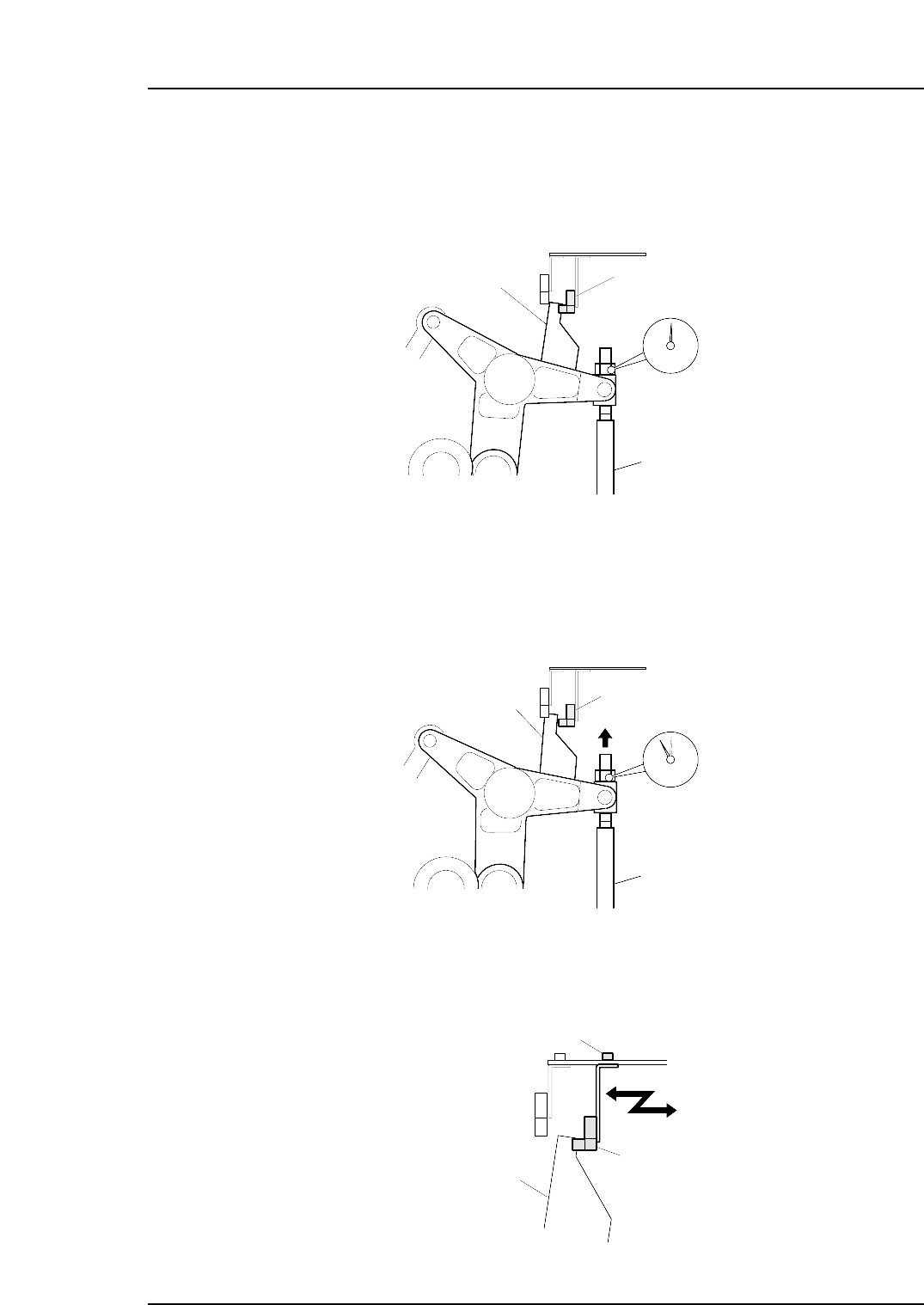
5. Place a dial gauge on the top end of the cam lever and set the gauge reading to
“0”. In this condition, the cam axis will be at its 180-degree position, and the
nozzle UP/DOWN rod will be at its DOWN limit position. Verify that the nozzle
DOWN limit sensor is ON (X033 ST9 CYLINDER LOWER-LIMIT is ON) at the
I/O screen.
6. While observing the dial gauge, rotate the cam axis in the forward direction to
raise the nozzle UP/DOWN rod. Adjust the sensor’s mounting position so that
the sensor switches OFF (X033 ST9 CYLINDER LOWER-LIMIT switches OFF)
when the rod has been raised 0.3 to 0.4 mm.
7. Adjust the sensor’s mounting position by loosening the sensor lock screw and
sliding the sensor in the front/back directions.
C7SM4035
Nozzle down limit sensor
Screw
Dog
C7SM4034
Nozzle down limit sensor (OFF)
Nozzle UP/DOWN rod
Rod raised 0.3 to 0.4 mm.
Dog
C7SM4033
Set the dial gauge to "0".
Nozzle down limit sensor (ON)
Dog
Nozzle UP/DOWN rod
Part 4 Chapter 1 Station Adjustments
Edition 2.4 4-1-33 CP-7 series Mechanical Reference
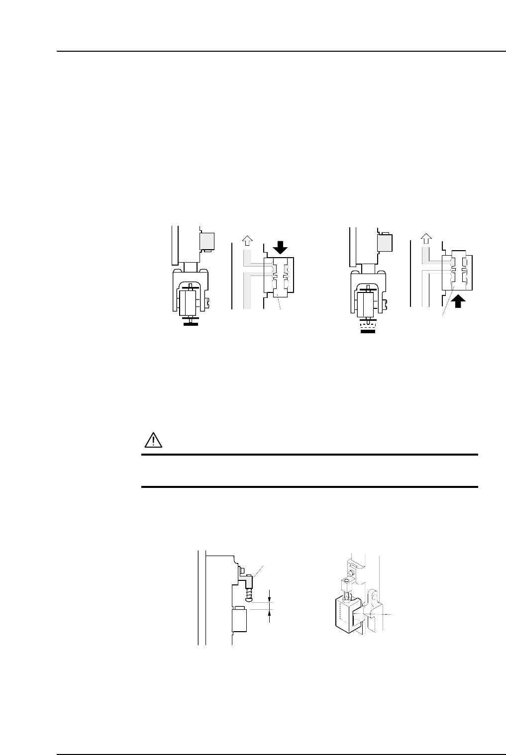
1.11 Mechanical Valve Switching (Station 9)
Point
The nozzle vacuum goes from ON to OFF with the movement of the mechanical valve at
station 9. Vacuum pressure inside the nozzle is released for part placement when the
valve closes. Ensure the part is placed on the production board.
1.11.1 Checking the Position of the Pin Bracket
1. Press the EMERGENCY STOP button to turn off the 200V power, leaving only the
100V power on.
WARNING
Always be sure to cut off the 200V power before carrying
out this work.
2. Ensure that distance A (as seen in the figure below) is 8.9 mm for all heads. Use a
special jig (Z9526DCPJ0371) to check this distance.
8.9 mm
Pin bracket
Jig
( Z9526DCPJ0371 )
C7SM4054a
A
C7SM4036a
Vaccum ON Vaccum OFF
Vaccum
Vaccum
Spool
Spool
<Spool pushed up><Spool pushed down>
Part 4 Chapter 1 Station Adjustments
Edition 2.4 4-1-34 CP-7 series Mechanical Reference