CP-7[732-742]-series Mechanical Reference(2.9E).pdf - 第195页
2. Manually rotate the rotary holder to select nozzle No. 6. At this time, the sensor reactions should be the same as shown below. 3. Rotate the rotary holder to select nozzle No. 2. At this time, the sensor readings sho…
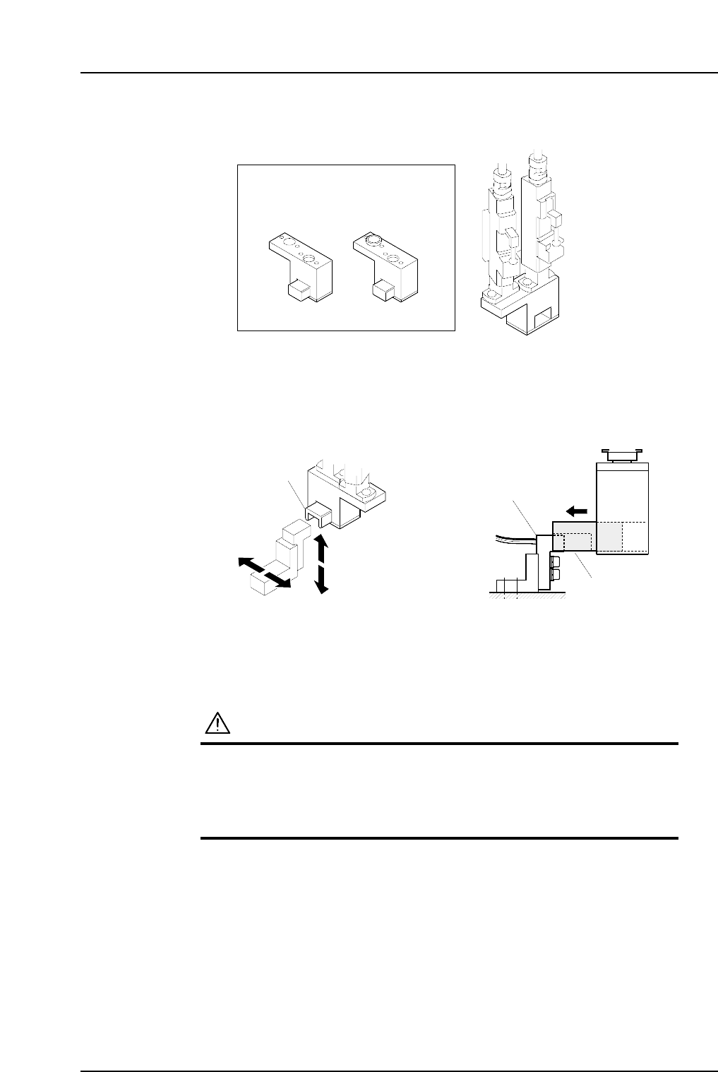
6. Attach the adjustment jig (for station 13) to the placing heads at stations 13 and 14.
Note: Do not turn the cam with the jig attached to the placing heads; otherwise the heads
might be damaged.
7. Adjust the sensor bracket position so that it can be smoothly inserted to the cavity
of the jig block.
1.14.2 Checking the Sensor Reaction
1. Press the EMERGENCY STOP button to take the 200V down to 100V.
WARNING
• Always be sure to cut off the 200V power before carrying
out any work.
• Exercise extreme caution when working on the machine if
the cam is not at its origin (0 deg.). Recoil of the cam
axis can endanger the operator.
Jig block
Jig block
Sensor bracket
C7SM4061
C7SM4060
ADCPJ8030 (CP-732E)
ADGPJ8050 (CP-742ME,CP-742E)
For ST13
13 st
14 st
For ST15
Adjustment jig
Part 4 Chapter 1 Station Adjustments
Edition 2.4 4-1-44 CP-7 series Mechanical Reference
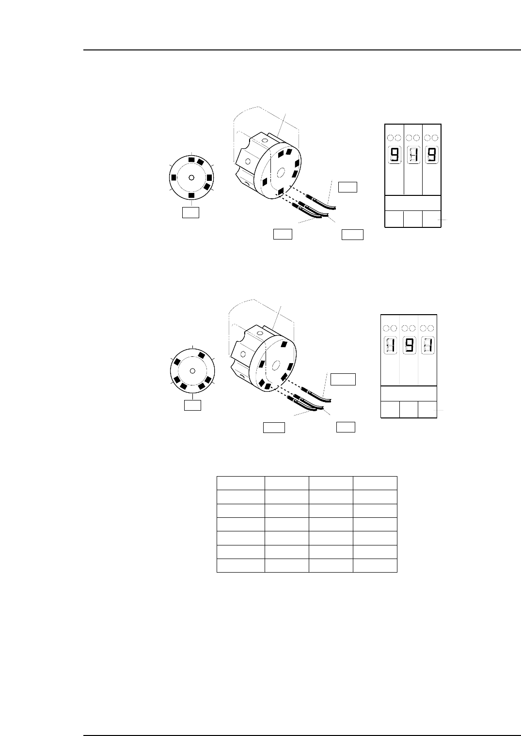
2. Manually rotate the rotary holder to select nozzle No. 6.
At this time, the sensor reactions should be the same as shown below.
3. Rotate the rotary holder to select nozzle No. 2.
At this time, the sensor readings should be the same as shown below.
4. Ensure that the sensors display for the other nozzles as shown below.
Nozzle 1
Nozzle 2
Nozzle 3
Nozzle 4
Nozzle 5
Nozzle 6
Sensor 1
ON
OFF
OFF
ON
OFF
ON
Sensor 2
OFF
ON
OFF
ON
ON
OFF
Sensor 3
OFF
OFF
ON
OFF
ON
ON
T001
Digital display
0,1 = Sensor OFF
8,9 = Sensor ON
Sensor 1
Nozzle
Sensor 2
OFF
Sensor 3
Rotary holder
ON
C7SM4045a
1
2
3
4
5
6
OFF
123
Amp front view
Sensor No.
Digital display
0, 1 = Sensor OFF
8, 9 = Sensor ON
13ST
123
Amp front view
Sensor 1
Nozzle
Sensor 2
OFF
Sensor 3
ON
Rotary holder
ON
1
2
3
4
5
6
Sensor No.
Digital display
0, 1 = Sensor OFF
8, 9 = Sensor ON
13ST
C7SM4044a
Part 4 Chapter 1 Station Adjustments
Edition 2.4 4-1-45 CP-7 series Mechanical Reference
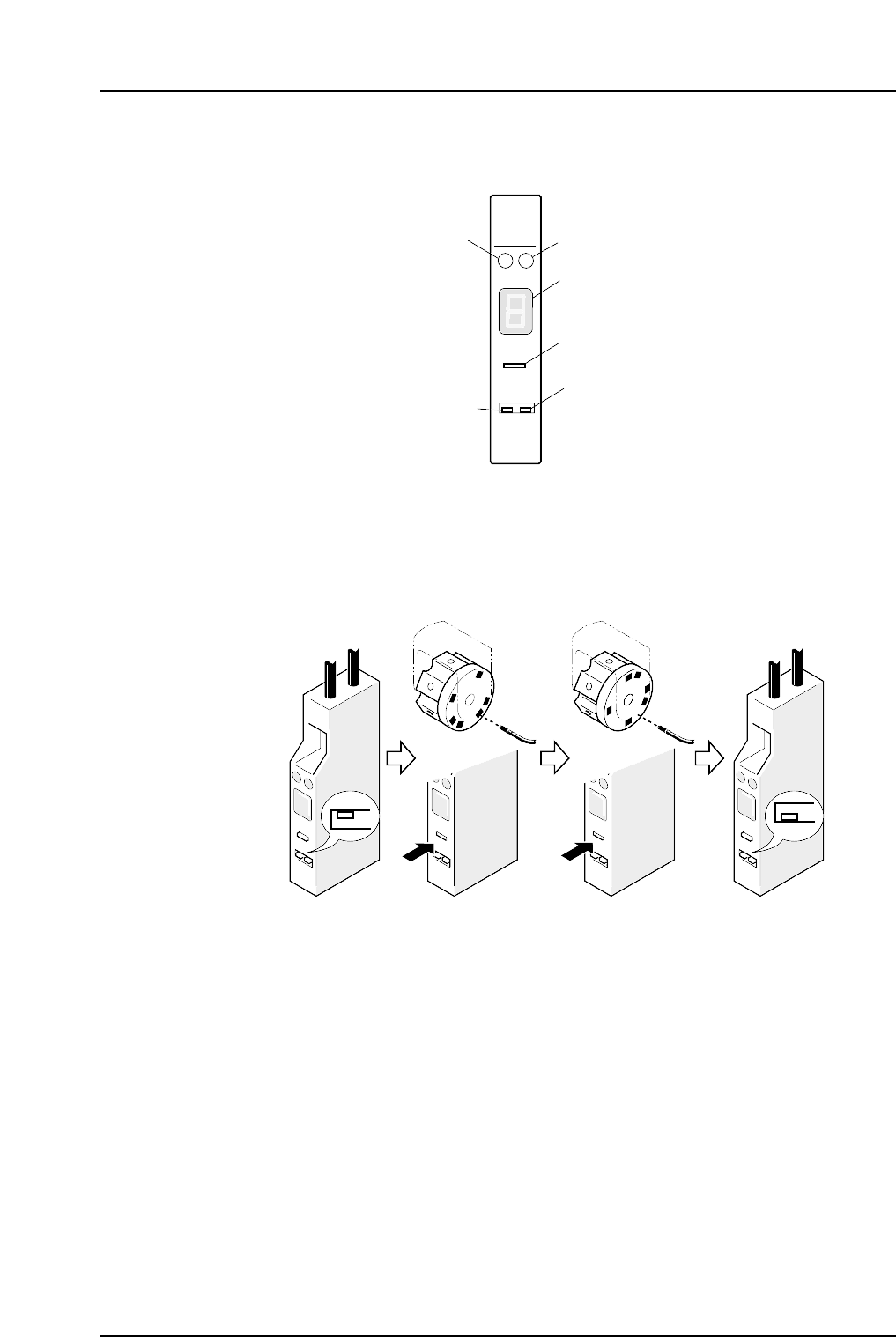
1.14.3 Sensor Sensitivity Adjustment
Remove the cover of the amp and follow the procedures below to adjust the sensor amp.
Note: Be careful not to drop the cover inside the machine.
Set the L-ON/D-ON switch to L-ON for the nozzle detection sensor.
1. Move the amplifier's mode change switch to the "SET" position.
2. Rotate the nozzle holder until the sensor light beam is adjacent to a dark part of
the dog and press “TUNING”.
3. Rotate the nozzle holder until the sensor light beam is adjacent to a metal part of
the dog and press “TUNING”.
4. Return the amplifier's mode changing switch to the "RUN" position.
At this time the sensitivity of the sensor can be checked on the digital display.
Digital display :
0 ~ 1: Stable interruption range
8 ~ 9: Stable light input range
If the display is within the stable range, setting is complete.
5. If the display is not within the stable range, check the items below and make the
necessary adjustments.
• Check the connections between the amplifier and the fiber optic cable.
• Check the position of the sensor.
SET
RUN
C7SM4047a
(1) (2) (3) (4)
SO
DELAY
TUNING
SET D-ON
RUN L-ON
HPY-T1
Green LED
Red LED
Digital display
Tuner
L-ON/D-ON
switch
Mode changing
switch
C7SM4046
Part 4 Chapter 1 Station Adjustments
Edition 2.4 4-1-46 CP-7 series Mechanical Reference