CP-7[732-742]-series Mechanical Reference(2.9E).pdf - 第207页
No. 2-4 2-5 2-6 2-7 Deviation between the feeder and machine pickup position. Check the pickup offset (X,Z) setting in Part data. The presence of parts or foreign matter , etc., on the device table or on the feeder'…

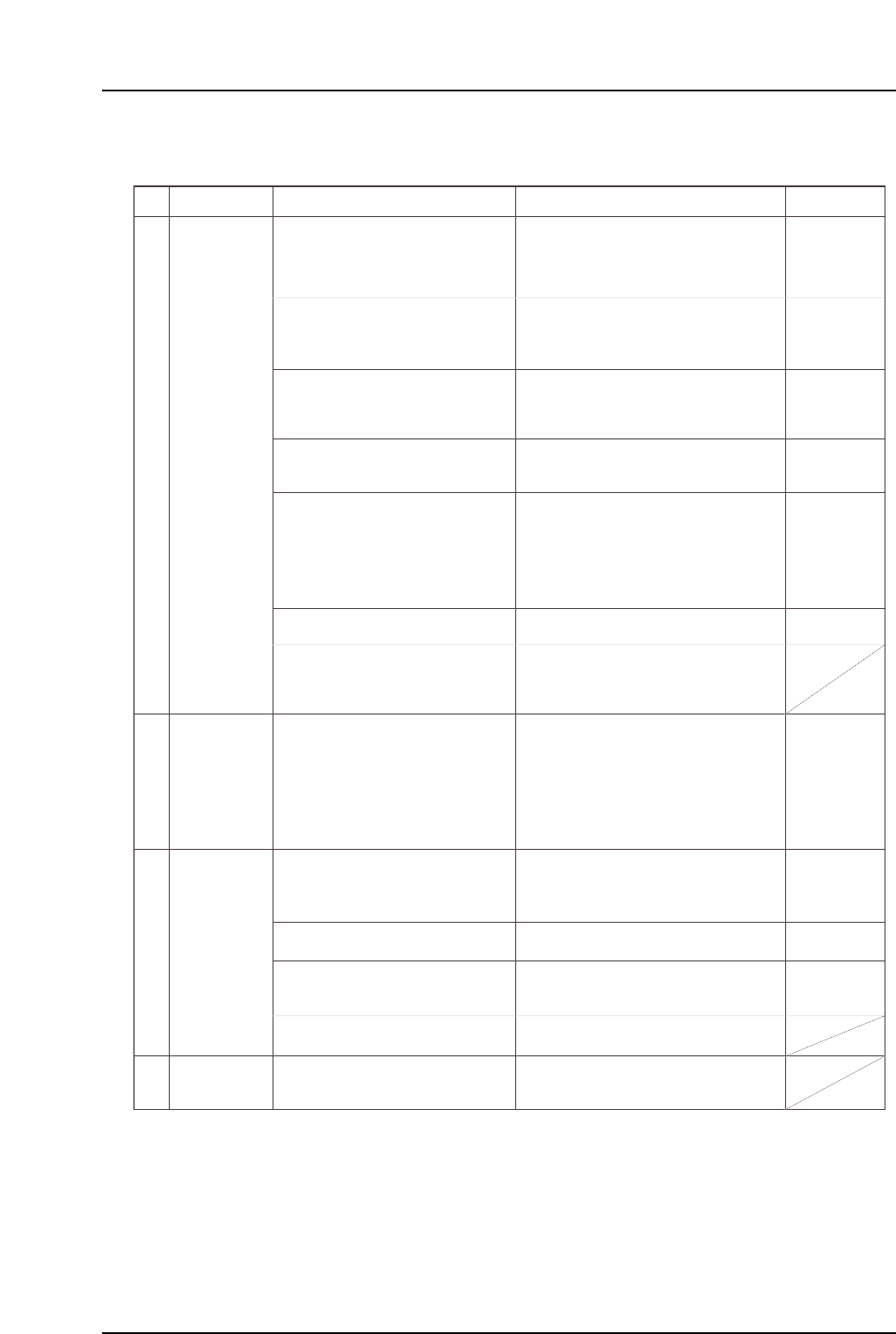
1.2 Pickup Errors
No.
2-1
2-2
2-3
Feeder top-film
does is not
taken up
correctly.
Improper feeder
tape feed.
Feeder set
improperly
Take-up will be abnormal if the top film is
not set correctly.
Set the top film correctly.
(Point) The top-film is not being peeled off at
the pickup point. Peel off the top-film
and verify that the take-up roller and
reel are set
correctly.
The top-film is not being peeled off at
the pickup point. Peel off the top-film
and verify that the
take-up roller and reel are set correctly.
A clogged tape leaf slit can back up the top-
film and prevent proper take-up.
Clean the tape leaf slit.
Take-up resistance increases if the take-up
roller fails to rotate smoothly.
Clean the inside of the take-up roller.
A deformed take-up spring reduces the take-
up force.
If the take-up spring is deformed,
replace it.
An excessively low reverse-direction torque
will reduce the take-up force.
Check the take-up reel's reverse-
direction torque.
If clearly low, replace the take-up reel.
Damage may occur or take-up may not be
correct if the take-up reel or aluminum
bracket is bent. This may also interfere with
surrounding feeders.
If the take-up reel or aluminum bracket
is deformed, replace it.
• An incorrect tape and feeder width or feed
pitch will prevent parts from being fed to
the proper position.
• A tape leaf which is unsuitable for the
nozzle size will cause parts to spring off the
tape.
• Check the tape and feeder feed
pitches, and set the tape on the
correct feeder.
• Use a tape leaf which is suitable for
the nozzle.
An incorrectly set tape leaf lock will cause
the tape leaf to lift, resulting in part
tombstoning and parts springing off the tape.
Set the tape leaf lock securely.
Parts and dust, etc., adhering to the inside
of the tape leaf will prevent the tape from
being pressed properly. Air-blow the tape
leaf before setting a tape.
Clean away parts and dust, etc., which
have adhered to the tape leaf.
A deformed tape leaf will cause part
tombstoning and parts springing off the tape.
Replace the tape leaf if it is deformed or
if it is not flat.
Tape feed resistance increases if the tape is
not set properly in the feeder.
Set the tape correctly.
Parts which are embedded in the sprocket
and stopper can prevent tape feed.
Clean away parts which are embedded
in the sprocket and stopper.
An incorrect feed lever height will prevent a
proper tapefeed stroke, and may disable
tape feed.
1) Check the feed lever height and the
feed movement.
2) When link assembly is deformed
replace any deformed parts.
The parts reel will not rotate correctly if the
reel holder is bent.
Replace the reel holder if it is bent.
Cause Remedy Remarks Ref. Page
FM: Part 2
Chapt 1
FM:
Supplement
FM:
Supplement
"Replacement"
FM: Part 3
Chapt 5
"5.5", "5.7"
FM: Part 3
Chapt 4 "4.9"
Chapt 5 "5.3"
FM: Part 2
Chapt 1
FM: Part 2
Chapt 2
FM: Part 2
Chapt 1
FM: Part 2
Chapt 5 "5.2"
FM: Part 3
Chapt 2 "2.2"
FM: Part 3
Chapt 2 "2.1"
FM: Part 3
Chapt 2 "2.2"
FM: Part 3
Chapt 5 "5.1"
FM: Part 3
Chapt 2 "2.4"
FM: Part 3
Chapt 4 "4.8"
Part 5 Chapter 1 Troubleshooting Table
Edition 2.7 5-1-3 CP-7 series Mechanical Reference
No.
2-4
2-5
2-6
2-7
Deviation
between the
feeder and
machine pickup
position.
Check the pickup offset (X,Z) setting in
Part data.
The presence of parts or foreign matter, etc.,
on the device table or on the feeder's L-guide
can prevent the feeder from being set in the
correct position.
Parts which have adhered to the ratchet can
cause pickup position deviations at regular
intervals. Air-blow the ratchet area before
etting the tape.
Gouges in the feeder's L-guide can prevent
the feeder from being set in the correct
position.
An unsuitable reference value will result in an
automatic offset of the pickup height.
Note: Machine adjustments can be performed
only by those with a Level 3 training.
Pickup position deviations may occur after
prolonged feeder use.
Check the pickup posiiton periodically.
Lubricate the ratchet area. Failure to
lubricate can result in ratchet and stopper
wear which will cause pickup position
deviations.
• A bent nozzle will cause pickup position
deviations, and may prevent pickup from
occurring properly.
• A stuck nozzle cannot reach the part,
making pickup impossible.
• A clogged nozzle will have a lower vacuum
force, and may prevent pickup from
occurring properly.
Poor spool motion can prevent parts from
being picked up properly.
A low vacuum force may prevent parts from
being pick up properly.
Cracks in hoses can prevent parts from
being picked up properly.
Clean away parts and dust, etc., which
have adhered to the device table and
feeder tape leaf.
Clean away parts and dust, etc., which
have adhered to the ratchet.
Use a grinder to flatten the gouges in
the feeder's L-guide.
Adjust the pickup position.
Adjust the ST1 pickup height.
1) Use the nozzle check command to
check for bent nozzles.
2) Verify that the nozzle spring-back
motion is smooth.
3) Verify that the nozzle is not clogged.
If a problem is found with any of the
above, replace the nozzle.
Measure the part height sensor's nozzle
height reference value.
Ensure that the pressure value on the
vacuum pump displays at most -40kPa.
Replace the pump parts if the value fails
to reach the prescribed range.
Replace mechanical valves where the
spool motion is not smooth.
Check the connection of the hose
between the vacuum pump and the
index unit.
Check the hose between the vacuum
pump and the index unit.
Reset the ST1 feeder's feed lever.
Defective nozzle.
Vacuum force is
too low.
The ST1 feeder's
feed lever has
been tripped.
Cause Remedy Remarks Ref. Page
FM: Part 3
Chapt 2 "2.3"
FM: Part 3
Chapt 2 "2.1"
FM: Part 3
Chapt 7
DT-651(E) Digitizer
with Image
Processing
Instruction Manual
FM: Part 3
Chapt 4 "4.9"
FM: Part 3
Chapt 4 "4.11"
M: Part 4
Chapt 1 "1.4"
M: Part 4
Chapt 1 "1.5"
M: Part 3
Chapt 3 "3.1"
M: Part 3
Chapt 3 "3.8"
M: Part 3
Chapt 3 "3.10"
T: Part 3
Lesson 2
"2.1.3"
U: Part 2
Chapt 4
"Carrying"
Part 5 Chapter 1 Troubleshooting Table
Edition 2.7 5-1-4 CP-7 series Mechanical Reference
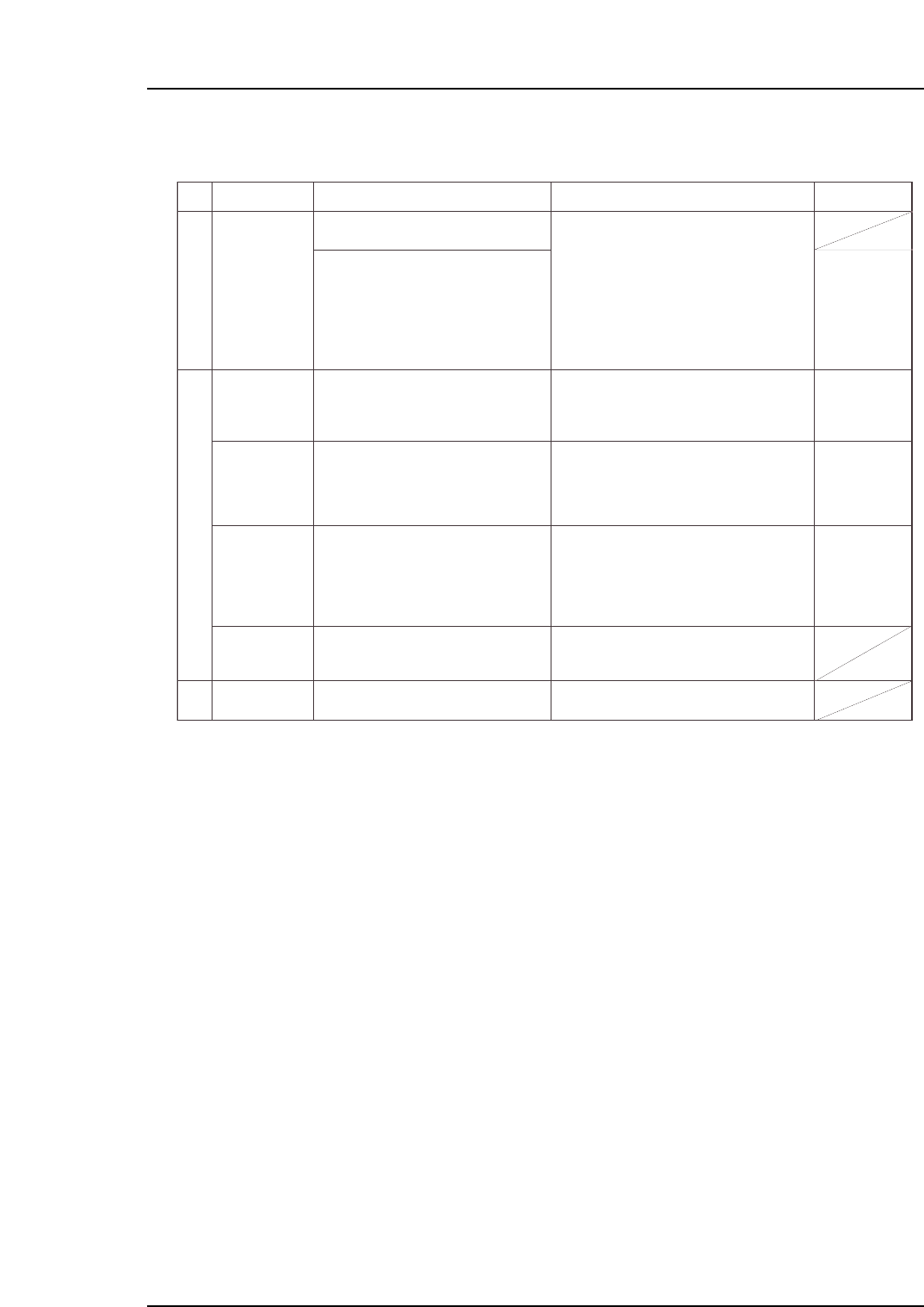
1.3 Vision Processing Errors
No.
3-1
3-2
3-3
M: Part 3
Chapt 1 "1.9"
Chapt 3
"3.1", "3.2"
T: Part 3
Lesson 2
"2.1.1", "2.1.2"
U: Part 2
Chapt 4
"Appearance",
"[Element]
window"
T: Part 3
Lesson 2
"2.1.1"
U: Part 2
Chapt 4
"Appearance"
M: Part 3
Chapt 1 "1.5"
Part size is
different from
Part Data
setting value.
Replace the error part with the correct
part type.
This error occurs because the part
information set in Part data is different from
the part on the machine.
If the problem is being caused by a soiled
nozzle, the vision processing error will occur
only when that soiled nozzle is used.
If the prism box surface is soiled, vision
processing errors will occur for almost all
parts.
Frequent vision processing errors may be
caused by slight differences between the
actual part dimensions and the dimension
settings. In such cases, measure the actual
part, and enter those dimensions as the
settings.
The brightness adjusting function is
supported from V1.18.
Enter the correct (error part's) part size,
part height, lead pitch, etc., settings in
Part data.
Check for dust, etc., around the
displayed image of the part causing the
vision processing error, the wipe the
prism box surface clean with a dry cloth
or cotton swab.
Measure the size of the part where
frequent errors are occurring, then enter
this correct size in Part data.
Replace the UV lamp if a "Replace UV
lamp" message displays after performing
a nozzle center measurement.
Refer to item 2 (Pickup Errors).
Check production information to see if a
specific nozzle is causing the vision
processing errors. If so, clean/replace
that nozzle, or replace its reflective seal.
Nozzle is soiled.
Prism box
surface is soiled.
The part size is
slightly different
from the Part
data setting.
UV lamp life has
expired.
Parts are not
being picked up.
Cause Remedy Remarks
Ref. Page
Part 5 Chapter 1 Troubleshooting Table
Edition 2.7 5-1-5 CP-7 series Mechanical Reference