CP-7[732-742]-series Mechanical Reference(2.9E).pdf - 第216页
2. Servo System T roubleshooting An AC servo system controls all servo axes in the machine. If there is a problem with the servo system, the machine displays an alarm code to notify the operator. This section describes a…

Notes:
Part 5 Chapter 1 Troubleshooting Table
Edition 2.7 5-1-12 CP-7 series Mechanical Reference
2. Servo System Troubleshooting
An AC servo system controls all servo axes in the machine. If there is a problem with the servo
system, the machine displays an alarm code to notify the operator.
This section describes alarm codes and inspection methods, and should be used as a reference for
troubleshooting and resolving problems.
2.1 Alarm Code Display
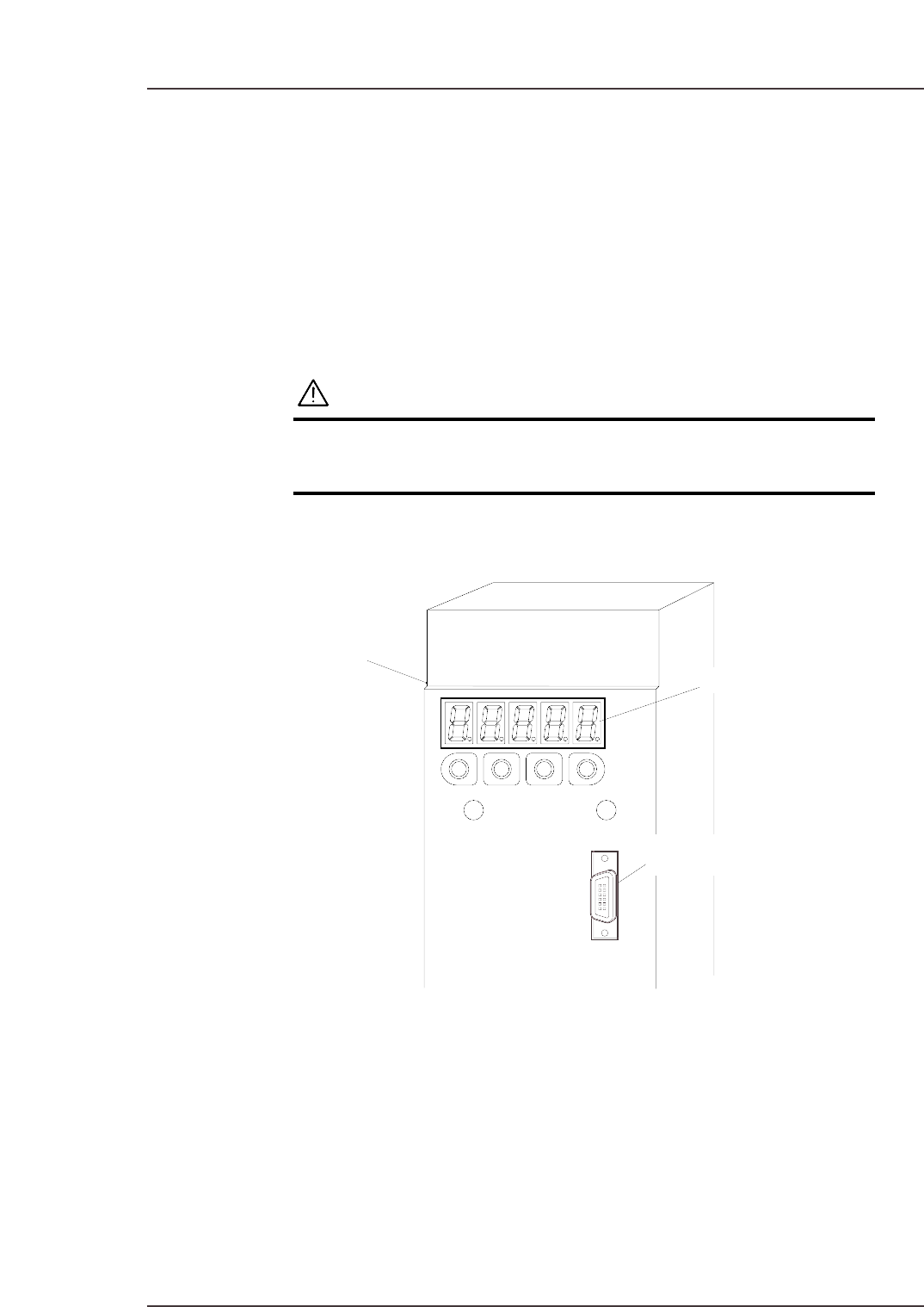
Each servo amp has an LED panel to display alarm codes.
The following illustrations show the location of each servo amplifier’s LED panel.
WARNING
The servo amplifier power terminal is high voltage.
Absolutely do not touch the servo amplifier power
terminal.
Note: To display the alarm code on the digital operator, connect the digital operator cable to the
servo amplifier (CN3 connector).
C7SM6001E
Servo amplifier
LED panel
Connector (CN3)
Part 5 Chapter 2 Servo System Troubleshooting
Edition 2.6 5-2-1 CP-7 series Mechanical Reference
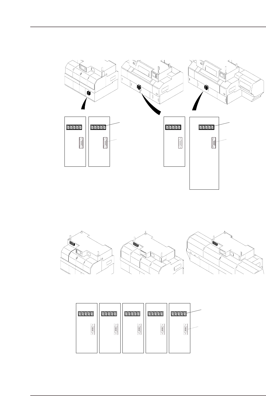
X- and Y-Axes Servo Amplifier Alarm Display
Rθ-, NC-, Fθ-, Pθ-, and NZ-Axes Servo Amp Alarm Display
C7SM6003
<CP-732E> <CP-742ME> <CP-742E>
CN3 connector
NZ-axisPθ-axisFθ-axisRθ-axis NC-axis
LED panel
C7SM6002
CN3 connector
CP-743E
CP-743ME
Y-axisZ-axisZ-axisY-axis
LED panel
CN3 connector
LED panel
<CP-732E> <CP-742ME> <CP-742E>
Part 5 Chapter 2 Servo System Troubleshooting
Edition 2.6 5-2-2 CP-7 series Mechanical Reference