CP-7[732-742]-series Mechanical Reference(2.9E).pdf - 第238页
Wiring the T ransformer 1. Open the transformer box cover. 2. Wire the transformer’s primary taps to match the supplied voltage. <CP-742E> T ransformer box T ransformer box T ransformer box C7SM5004a <CP-732E>…
3. Electrical Power Supply & Transformer Wiring
Point
Wire the transformer so that its voltage matches the power supply voltage.
Procedure
DANGER
Verify that the external power supply is off before
performing this procedure.
Connecting the Power Supply
The power capacities are indicated below. Be sure to connect the machine to a power
supply which exceeds this capacity.
• CP-732E : 8.5KVA
• CP-742ME: 9.0KVA
• CP-742E : 9.5KVA
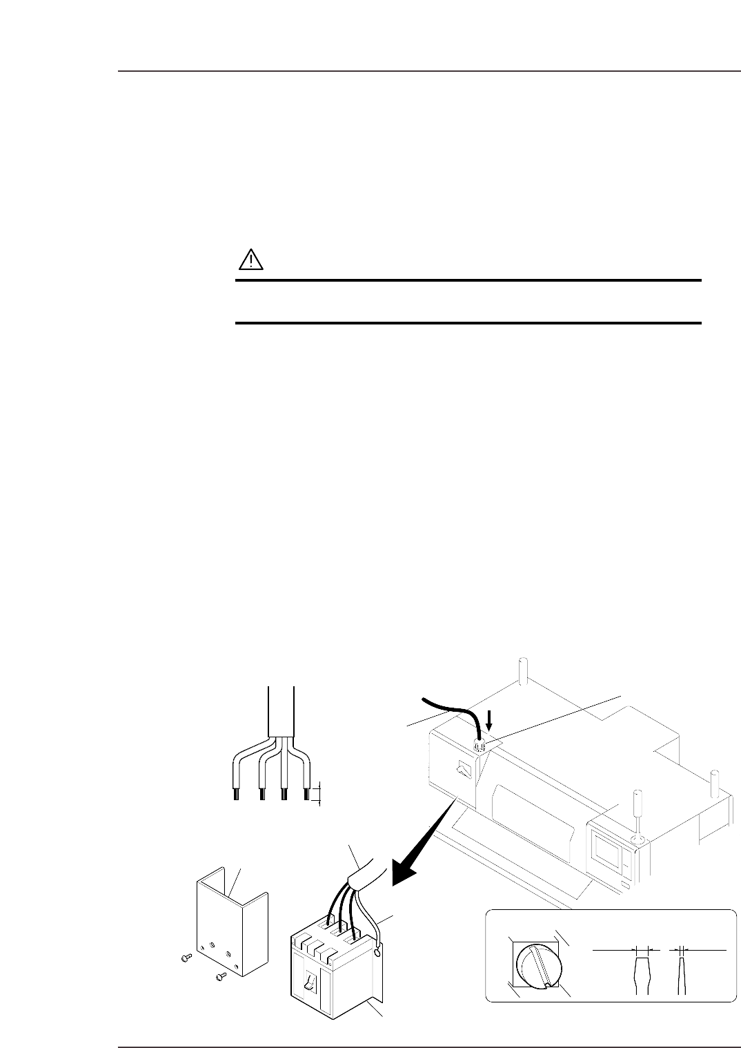
1. Open the main breaker box, then remove the transparent terminal cover.
2. Feed the power cable into the main breaker box from the power cable inlet located
at the top of the main breaker box.
3. Connect the ground cable to the dedicated ground terminal.
4. Connect the 3-phase cable to the main breaker and tighten to the prescribed
torque.
Terminal screw tightening torque: 5.8 N⋅m (58 kgf⋅cm)
Note: Terminal screws should be tightened periodically.
5. After connecting the cable, secure it with the cable lock nut located at the power
cable inlet.
Cable lock nut tightening torque: 7.5 N⋅m (75 kgf⋅cm)
Power cable
Cable lock nut
20 mm
Terminal
screw
Recommended driver
8.0mm 1.0mm
Main breaker
Transparent terminal cover
Three-phase electric wire
Ground wire
C7SM5003
Part 6 Chapter 3 Electrical Power Supply & Transformer Wiring
Edition 2.6 6-3-1 CP-7 series Mechanical Reference
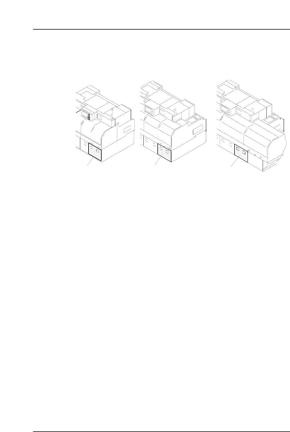
Wiring the Transformer
1. Open the transformer box cover.
2. Wire the transformer’s primary taps to match the supplied voltage.
<CP-742E>
Transformer box
Transformer box
Transformer box
C7SM5004a
<CP-732E> <CP-742ME>
Part 6 Chapter 3 Electrical Power Supply & Transformer Wiring
Edition 2.6 6-3-2 CP-7 series Mechanical Reference
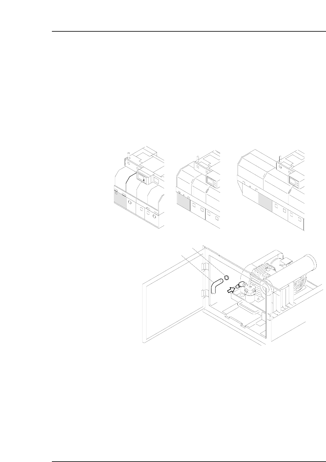
Checking the Three-phase Connections
Perform the following procedure to verify that the three-phases are properly connected.
1. Turn the 200V power on.
2 Log in the machine.
3. Press the [AUTO] button (but do not press START).
Note: Do not press the START button.
The vacuum pump begins operating when [AUTO] is pressed, so disconnect the
hose to verify that suction exists. If there is suction, this indicates that the wiring is
correct and the motor is rotating in the correct direction. If the air flow is reversed
(air is blowing out instead of in), then turn the main power off and reverse the three-
phase power cable’s U-phase and V-phase connections, then try again.
Caution: To avoid leaks, the hose should be pushed firmly into position, and then secured in
position with the hose band.
C7SM5005a
air
Hose
Hose band
<CP-742E><CP-732E> <CP-742ME>
Part 6 Chapter 3 Electrical Power Supply & Transformer Wiring
Edition 2.6 6-3-3 CP-7 series Mechanical Reference