CP-7[732-742]-series Mechanical Reference(2.9E).pdf - 第68页
13 and 15 inch parts reels should be positioned using the three rubber stoppers. When setting, ensure that the feeder base and reel itself are positioned in the same slot. Correct parts supply will not be possible if fee…
3. Setting the Feeders
Point
Feeders must be set on the pallets in the correct manner in order for the nozzles to pick
up parts. Refer to the CP Feeders Mechanical Reference (MEC-CPFDR-x.xE) for details.
Procedure
WARNING
Turn the main power off before performing this procedure.
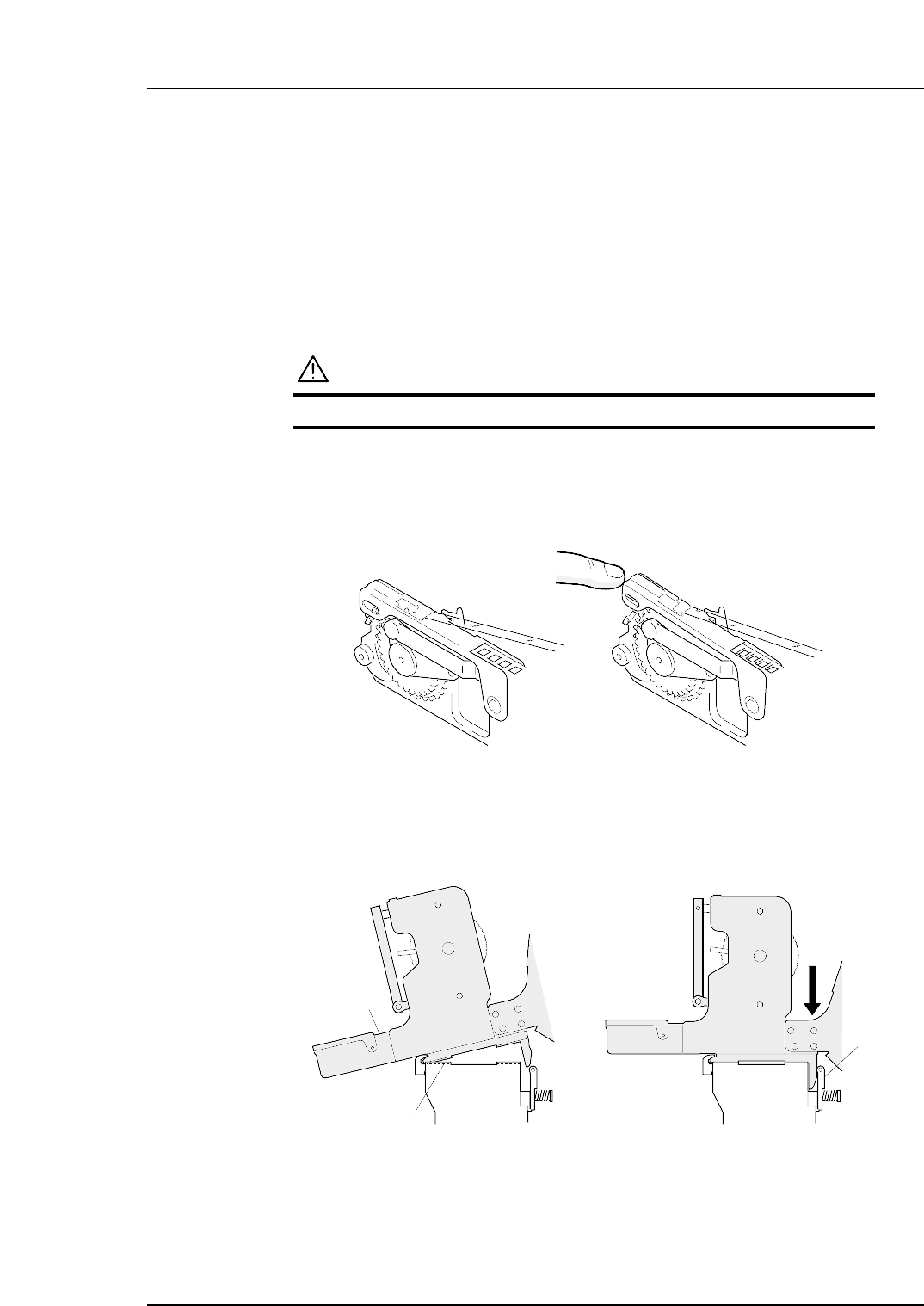
1. Verify that the tape guide is not deformed.
2. Place the various part tapes in their dedicated feeders. If a part tape is placed in
the wrong feeder, the tape guide may not close properly.
3. Insert the catch on the base of the feeder into the channel beneath the guide. Push
the feeder forwards and then press the back of the feeder down to clamp it firmly
in position.
Clamper
Guide channel
Feeder
C7SM2009
C7SM2005a
Correct Incorrect
Part 2 Chapter 3 Setting the Feeders
Edition 2.4 2-3-1 CP-7 series Mechanical Reference
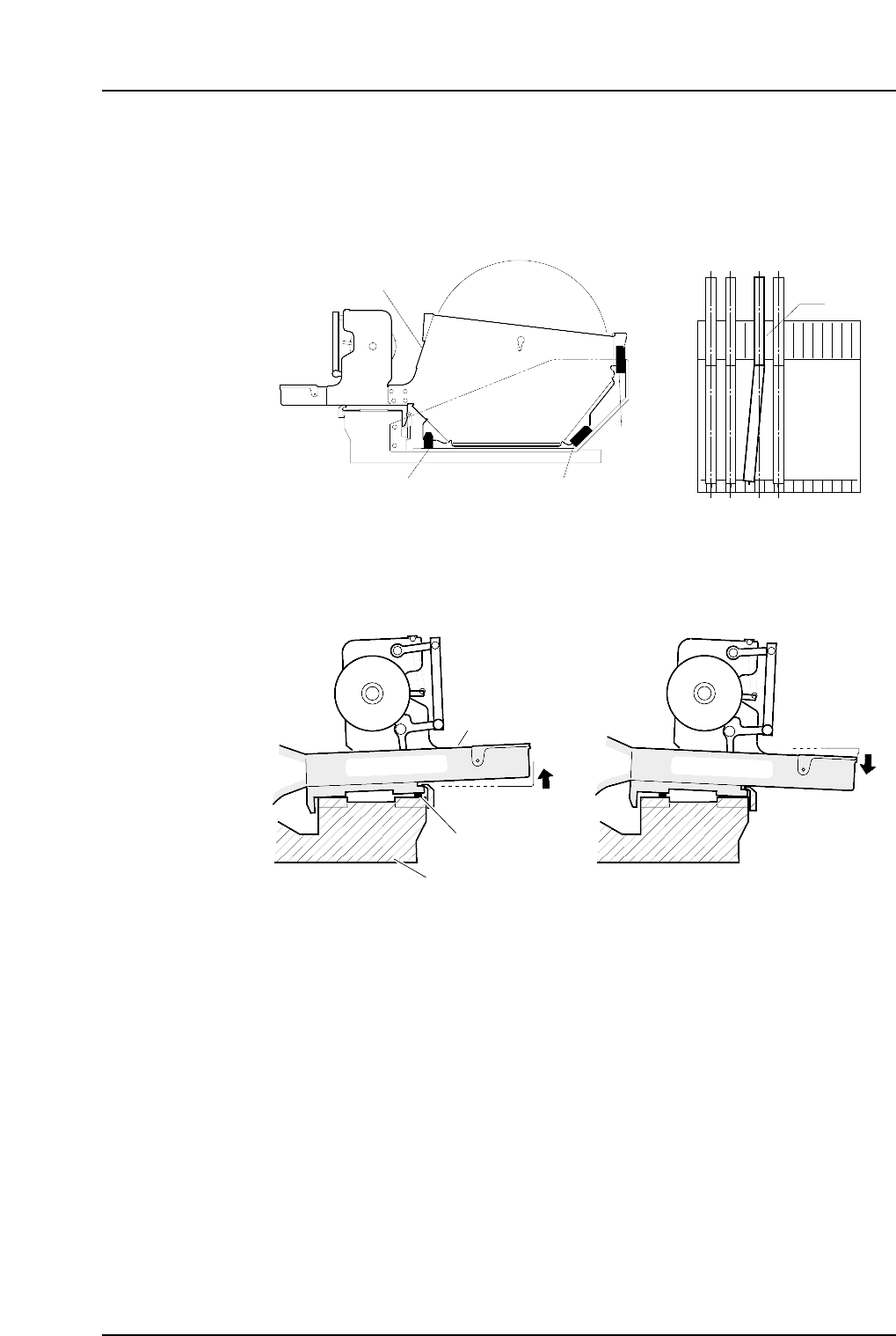
13 and 15 inch parts reels should be positioned using the three rubber stoppers.
When setting, ensure that the feeder base and reel itself are positioned in the same
slot. Correct parts supply will not be possible if feeders are incorrectly set as
shown in the figure below.
4. When setting a feeder on a pallet, be sure that there is no foreign matter (waste
tape, etc) between the feeder and the pallet. Remove any foreign matter which has
adhered to the pallet grooves or to the bottom of the feeder.
Waste tape
Pallet
Feeder
C7SM2006
Reel holder
Rubber brace Rubber brace
Rubber brace
View of pallet from above
C7SM2010
A
Part 2 Chapter 3 Setting the Feeders
Edition 2.4 2-3-2 CP-7 series Mechanical Reference
4. Changing Pallets
Point
The PCU (Pallet Change Unit) enables batch changes of feeder pallets.
Procedure
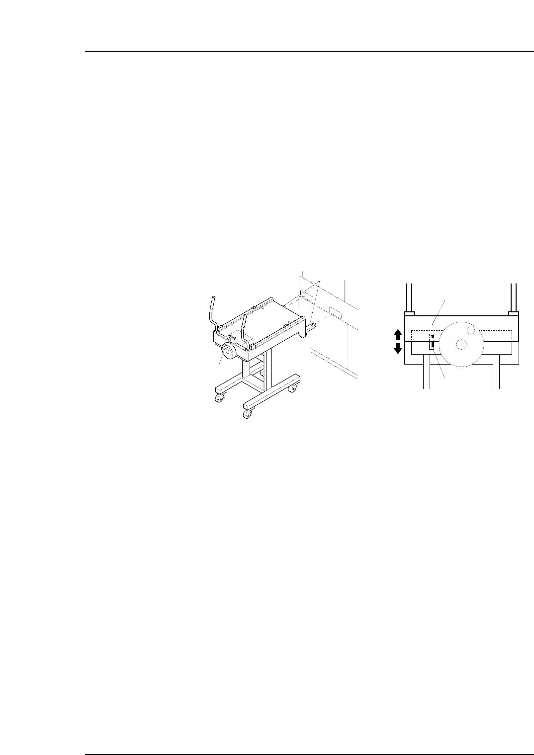
Pallet unloading
1. Align the height of the PCU forks (at the end of the PCU) with the fork slots on the
machine. Turn the handle and raise the upper section of the PCU.
Note: Use the guide seal at the side of the handle as a reference when adjusting the height
of the forks. Adjust so that the lower surface of the plate falls within plus or minus 10
mm of the standard value.
2. Push the PCU to insert the forks into the machine, then clamp it with the [Stage1
Clamp] command.
Note: The following explanation describes the D1-axis (stage 1) pallet change.
3. Close the rear door and select the [Stage1 Start] command, then press START. The
D-axis pallet moves to the change position and is unclamped.
4. Open the rear door and pull the pallet out of the machine and onto the PCU.
Caution:
1. Remove the pallet slowly.
2. To avoid damage to the door stoppers, the door should be opened and closed with
care.
5. Select the [Stage1 Unclamp] touch-panel command, then slowly retract the loaded
PCU.
Caution: Exercise extreme care when using the PCU to move a fully loaded pallet. A
dropped pallet may result in serious injury or damage to the machine.
C7SM2008a
Handle
Forks
Plate
Guide seal
Part 2 Chapter 4 Changing Pallets
Edition 2.0 2-4-1 CP-7 series Mechanical Reference