CP-7[732-742]-series Mechanical Reference(2.9E).pdf - 第72页
Notes: Part 2 Chapter 5 Setting the Panel Positioning Pins Edition 2.2 2-5-2 CP-7 series Mechanical Reference
5. Setting the Panel Positioning Pins
<CP-742ME/CP-742E>
Point
When using pin reference panels, set the positioning pins so that they match the size of
the panel to be loaded. The pins to be set are listed below.
*: Do not change the position of the panel 1 reference pin.
Procedure
WARNING
Turn the main power off before performing this procedure.
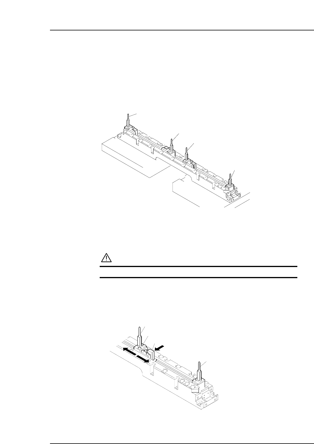
First, push the panel 1 movable pin holder’s lock lever in the direction of the arrow
and move the pin holder so that it matches the panel’s pin pitch. Then,
considering the distance between panel 1 and panel 2, decide the positions for the
panel 2 reference pin and panel 2 movable pin.
Pin holder
Lock lever
Panel 1 reference pin
Panel 1 movable pin
C7SM2014E
C7SM2013E
Panel 1 movable pin
Panel 1 reference pin *
Panel 2 reference pin
Panel 2 movable pin
Part 2 Chapter 5 Setting the Panel Positioning Pins
Edition 2.2 2-5-1 CP-7 series Mechanical Reference

Notes:
Part 2 Chapter 5 Setting the Panel Positioning Pins
Edition 2.2 2-5-2 CP-7 series Mechanical Reference
6. Adjusting the Position of the Panel 2 Stopper
(During Double Panel Production)
Point
When conducting double panel production, the positions of the in- and out-conveyors’
Panel 2 stopper must be adjusted to match the dimensions of the panel being used.
Procedure
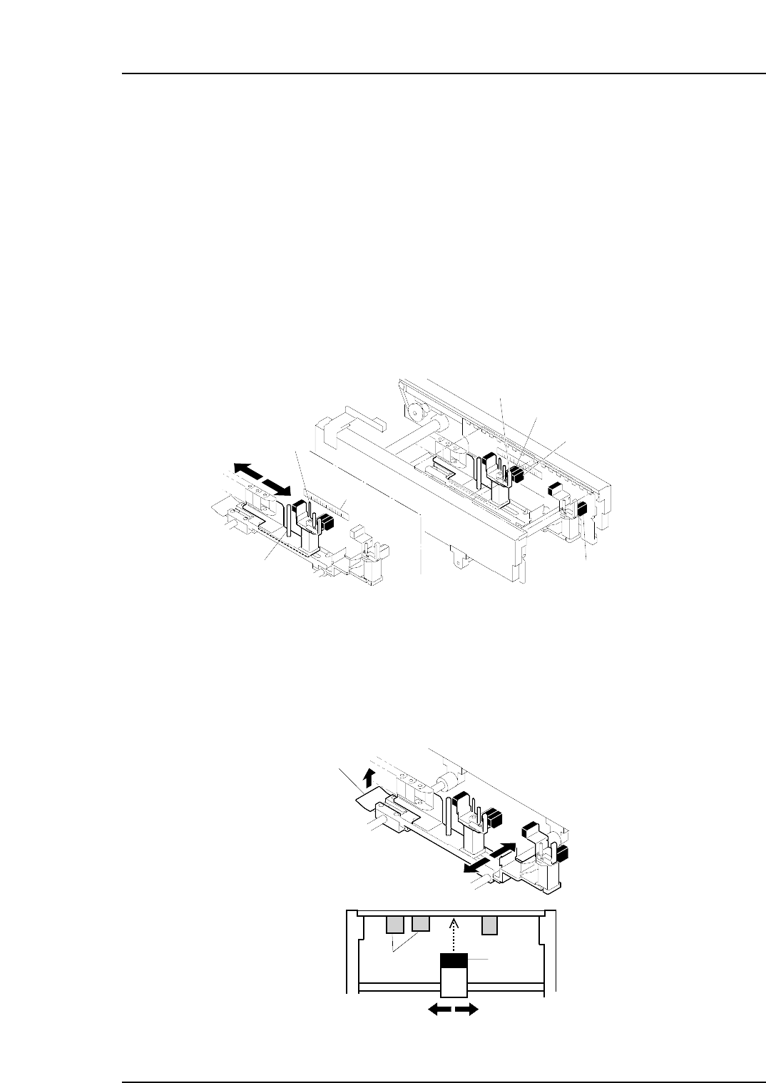
Adjusting the X-axis direction
Loosen the adjustment bolt and slide the Panel 2 stopper so that it is aligned with the
scale measurement that equals the panel length. Then, retighten the adjustment bolt.
Note: The possible panel lengths for double panel production are as follows.
CP-732E..................................................80 ~ 170 mm
CP-742ME / CP-742E.............................80 ~ 220 mm
Adjusting the Y-axis direction
Release the lock by pulling the lock lever and adjust the position of the sensor. Set the
sensor so that there will be no interference with already placed parts on the reverse side
of the panel.
C7SM2012E
Lock lever
Y direction
Already
placed parts
Sensor
C7SM2011E
Panel 2 stopper
Adjustment bolt
Scale
Slide lever
Gap check sensor
Panel 2 arrival check sensor
Panel 1 arrival check sensor
Part 2 Chapter 6 Adjusting the Position of the Panel 2 Stopper
Edition 2.2 2-6-1 CP-7 series Mechanical Reference