1OM-1626-001_w.pdf - 第185页
1OM-1610 5-4 1. Specications : Chap.5 091 1-001 Item Description Example : T o correct the positional deviation covering the whole area of PCB (PCB Overall Correction) T o improve recognition accuracy , put ducial mark…
1OM-1610
5-3
1. Specications : Chap.5
0911-001
Item Description
9. Correction Method
for PCB Location
PEC Recognition
•
By recognizing the ducial marks using the PEC camera, positional
deviation covering the whole area of PCB and expa
nsion of the printed
patterns on PCB can be corrected.
•
To correct the positional deviation covering the whole area of PCB,
ducial marks must be put on two or three places of PCB (Zones 1
through 5). Two ducial marks are required for each unit PCB of a
multi-unit PCB.
•
T
o correct the positional deviation of component placement points, put
one to two ducial marks on the PCB. In this case, it is recommended
that two ducial marks be located symmetrically such that the center
of gravity (the center of the ducial marks) becomes the center of the
component placement point.
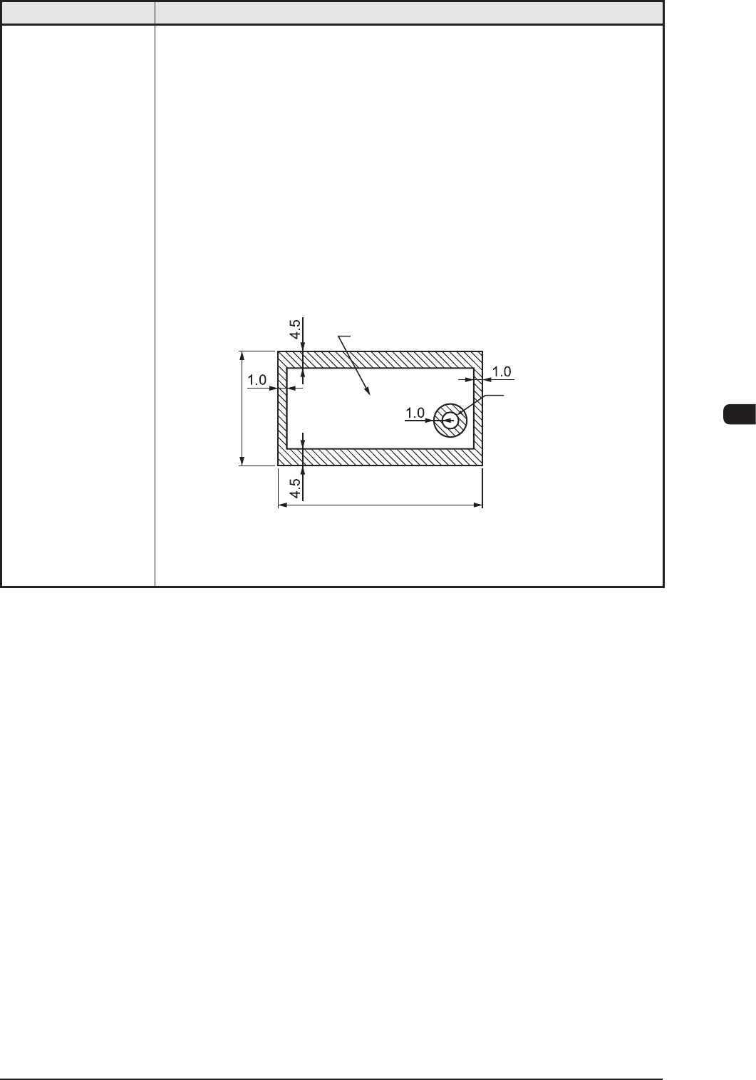
(Front Side of Machine)
Range where a fiducial mark can be put
Hole, etc.
50.0 to 610.0
50.0 to 460.0
Unit : mm
T1E1-3
1OM-1610
5-4
1. Specications : Chap.5
0911-001
Item Description
Example :
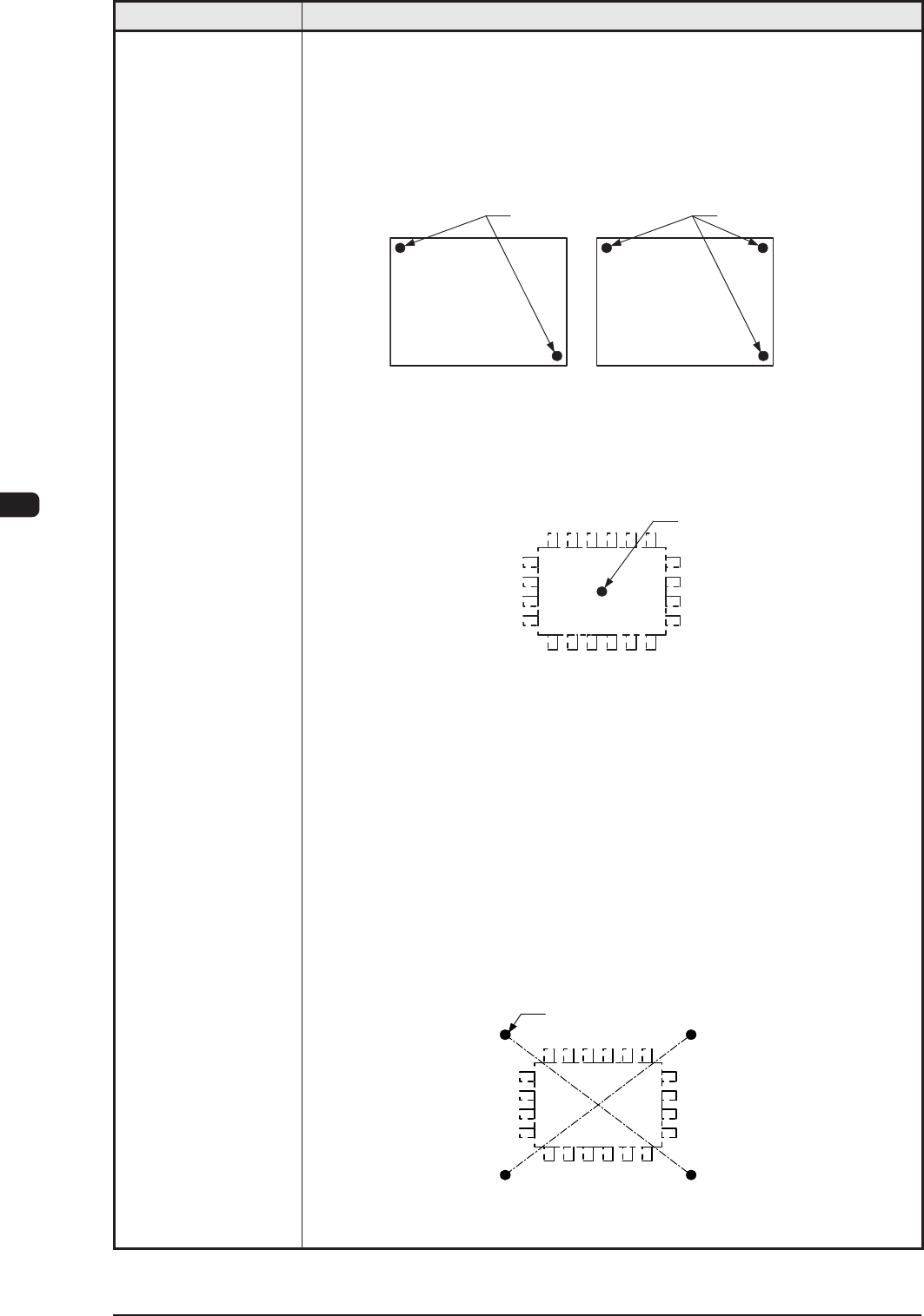
To correct the positional deviation covering the whole area of PCB (PCB
Overall Correction)
To improve recognition accuracy, put ducial marks diagonally on two
places of PCB when the 2-point recognition mode is selected. In the case of
3-point recognition mode, put two ducial marks diagonally and one ducial
mark close to one of the remaining corners.
PCB
Fiducial Mark
PCB
Fiducial Mark
Example 1 : To correct the positional deviation of component placement
points (1-point recognition)
Put a ducial mark on the center of component placement point
or a desired point around the center.
Recommended Position : Center of Component Placement Point
Fiducial Mark
Example 2 : To correct the component placement point
(2-point recognition)
Put ducial marks on the desired two points around the center of
component placement point.
Recommended Position
:
Point Symmetry
It is recommended that two points
(ducial marks) should be located
symmetrically on both sides of the
center of the placement position.
(A-A'/B-B')
•
These ducial marks are used to correct the component position and the
theta (angle).
The 2-point recognition is effective to correct deviated and distorted part
of the printing patterns.
Fiducial Mark
A
A'B
B'
T1E1-4
1OM-1610
5-5
1. Specications : Chap.5
0911-001
Item Description
10. Conditions of
PCB before
Placement
(Regulation
of Component
Height)
Dual Mode Single Mode
Height of
Previously-Placed
Component
Upper Surface
12.7 mm / High-Speed Head
25.4 mm / Multifunctions Head
Lower Surface
30 mm
Dead Space
Upper Surface
3.0 mm
Lower Surface
3.0 mm
3.0
3.0
φ
φ
3.0
3.0
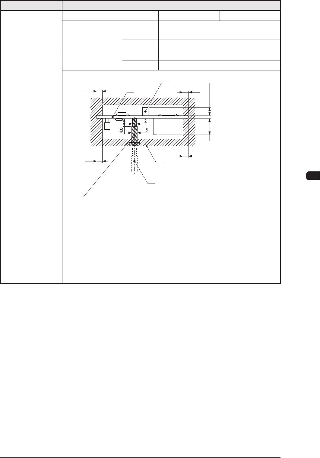
PCB
Component
(Front Side of Machine)
Previously-placed
Components Unallowed
Range
PCB Support Pin (At this position
when PCB is transfered.)
PCB Support Pin (Several Places)
Max. 30.0
When the High-Speed
Head is used:
Max. 12.7
When the Multi-Functional
Head is used:
Max. 25.4
Unit : mm
Notes
: (a) PCB support pin position can be moved "10mm" by "10mm" .
(b) Set the PCB support pin on the position where it does not touch
the already placed component.
(c) The gure shows that the PCB is being supported.
(d) The dimensions are those for design reference.
Leave some room for the actual setting.
T1E1-5