00195011-01.pdf - 第11页
Installation Manual, Station Software Version 408.01 Edition 03/2006 3.2.2 Network configuration S23, F5 HM, CS, CF m achine SIPLACE Pro Station com puter Maschine contro ller 100 Base-T Switch 100 Base-T privat e networ…
Installation Manual Station Software Version 408.01
3.2 Hardware components
3.2.1 Overview
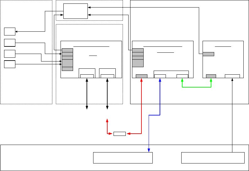
The following diagram shows the hardware components of the computer system for the various
machine types:
Station computer
Hardware components of SIPLACE S 23, F5 HM, CS and CF computer system
Monitor
Videomux
Keyboard
Mouse
Touch-
screen
Station computer
Local control / peripherals
Camera systems
(PCB camera, component camera,
RV camera)
SIPLACE LAN
(line)
Customer LAN
(GEM)
Machine
Switch
VGA
COM 1
COM 2
KBD /
Mouse
Desktop
Celeron 2.0 GHz, 256 MB
20 GB HD, FD, CD
USB
Machine controller
1 x COM352
LAN 1
VGA
COM 1
COM 2
KBD /
Mouse
CAN
VISION
4 x camera
HS3L
ICOS
MVS340
HS3L
Sicomp AMS M54
PI 100 MHz, 32 MB
504 MB HD, FD, CD
VGA
i865G Gbit
LAN
LAN 1
Intel, PRO
1000/MT
LAN 2
Control unit
Fig. 3-1: Hardware components of the computer system for the SIPLACE S23, F5 HM, CS and CF
10 of 104
Installation Manual, Station Software Version 408.01 Edition 03/2006
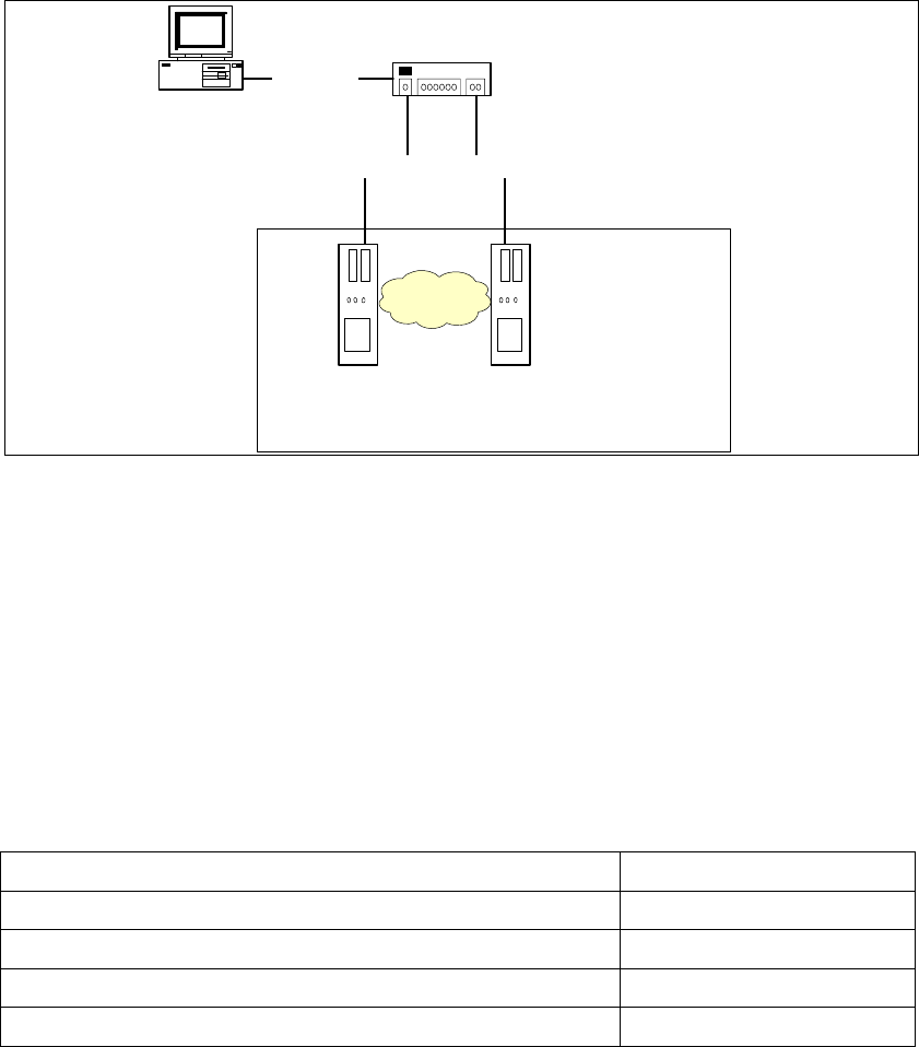
3.2.2 Network configuration
S23, F5 HM, CS, CF machine
SIPLACE Pro
Station computer Maschine controller
100 Base-T
Switch
100 Base-T
private network
10 Base-T
Fig. 3-2: Network connections between the machine and SIPLACE Pro
A separate private network (100 Mbit) is set up between the station computer and the machine
controller via a subnet mask.
Fixed IP addresses for the station computer and the machine controller can thus be assigned for all
SIPLACE machines. These IP addresses are not known outside the private network, for instance in
the SIPLACE LAN.
These IP addresses need not be further configured by the operator while the station software is
being installed.
IP address, station computer
192.168.255.249
IP address, machine controller
192.168.255.250
Subnet mask, station computer/machine controller
255.255.255.248
IP address range, SIPLACE LAN
172.22.xxx.xxx
Subnet mask, SIPLACE LAN
255.255.0.0
Table 3-1: Network configuration
11 of 104

Installation Manual Station Software Version 408.01
3.2.3 Station computer
3.2.3.1 Station computer CS und CF
SCENIC C610 i 865GV
Name
Celeron ® CPU 2.80 GHz
CPU / clock frequency
256 MB (248MB)
RAM memory
40 GB (38.xxx MB)
Hard disk
Yes
CD-ROM drive
3.5“, 1.44 MB
Floppy drive
yes
USB interface
1 x 10/100Base-T
Network
2 x 10Base-T
6-port hub
Table 3-2: Station computer hardware
3.2.3.2 Station computer S23 und F5 HM
SCENIC N 320
Name
Celeron ® CPU 2.80 GHz
CPU / clock frequency
256 MB (248 MB)
RAM memory
40 GB (38.xxx MB)
Hard disk
Yes
CD-ROM drive
3.5“, 1.44 MB
Floppy drive
yes
USB interface
1 x 10/100Base-T
Network
1 x 10Base-T
Table 3-3: Station computer hardware
3.2.4 Machine controller MC54 for CS, CF, S23 and F5 HM
Sicomp AMS M54
Name
566 MHz
CPU / clock frequency
32 MB
RAM memory
20 bis 40 GB
Hard Disk
Yes
CD-ROM drive
3.5“, 1.44 MB
Floppy drive
1 x 10/100Base-T
Network
Table 3-4: Machine controller hardware
12 of 104