00196497-07_SM_SXDX12_en.pdf - 第102页
Service Work Conveyor Gantries 3.4.14 Replacing the PCB Camera [03075363-xx] 102 Service Manual SIPLACE SX1/SX2/DX1/DX2 FS02 3.4.14 3 . 4 . 1 4 R e p la c in g t h e P C B C a m e r a [ 0 3 0 7 5 3 6 3 - x x ] Replacing …
Service Work Conveyor
3.4.13 Replacing the Y Axis Sensor Module [03064608-xx] Gantries
Service Manual SIPLACE SX1/SX2/DX1/DX2 FS02 101
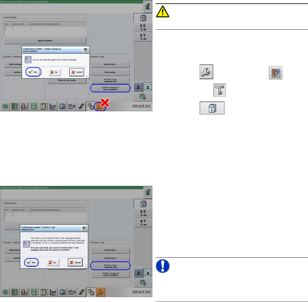
CAUTION!
Do not go to the "Fast Head Exchange" menu!
► Close the machine safety circuit.
► Log in as SIPLACE (customer)
(possible from SW706.1 SP2 HF2 and SW707.0).
► Click on the button and then the button.
► Select the gantry .
► Click on the button.
► Click on the Confirm Change of Sensor Module Y but-
ton and confirm the following message with Yes.
⇨ The gantry data already in the machine data will
now be written to the EEPROM of the new sensor
module.
► The machine will start a reference run. You may need
to press the START button.
► Click on the
Restore Y Axis Mapping Data button and confirm the
following message with Yes.
⇨ The gantry data already in the machine data will
now be written to the EEPROM of the new sensor
module.
► Switch the machine off and then on again.
⇨ Production can now be restarted.
NOTICE!
Y mapping can now be performed via the calibration
menu.
Duration: 1 min.
Service Work Conveyor
Gantries 3.4.14 Replacing the PCB Camera [03075363-xx]
102 Service Manual SIPLACE SX1/SX2/DX1/DX2 FS02
3.4.14
3.4.14 Replacing the PCB Camera [03075363-xx]
Replacing the PCB Camera [03075363-xx]
Parts, equipment and tools
▪ PCB camera (TYP34) 28 digital RK [03075363-xx] (standard)
▪ PCB camera (type 34HU) [03102921-xx] (for Twin VHF on 40mm gantry)
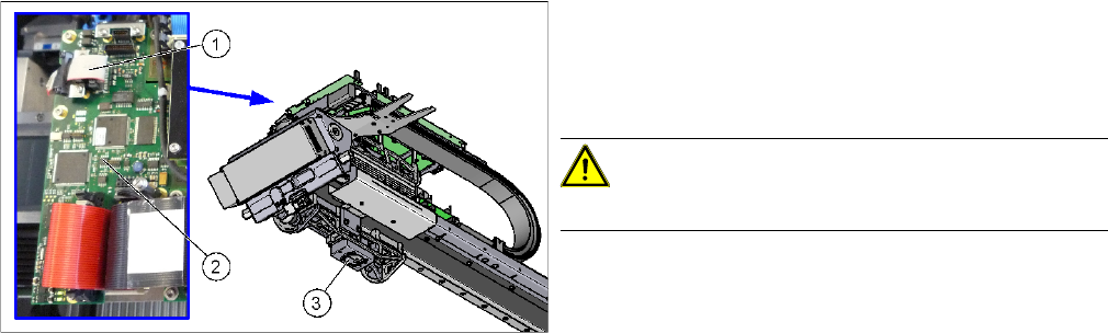
Overview
Removal
► Switch off the machine, disconnect it from the power supply and secure it to prevent unauthorized
reactivation. Observe the instructions in section "1.2 Preparatory Work..." [ ➙ 13].
► Unplug the PCB camera connector on the Vision board spread spectrum.
► Unplug the cable from the assembly plate. Open the corresponding cable ties to help you, if needed.
► Loosen the four screws fastening the PCB camera and remove it from the machine.
1. Connection of PCB camera to the Vision board
spread spectrum
2. Vision board spread spectrum
3. PCB camera
CAUTION!
Do not dismantle the PCB camera!
Service Work Conveyor
3.4.14 Replacing the PCB Camera [03075363-xx] Gantries
Service Manual SIPLACE SX1/SX2/DX1/DX2 FS02 103
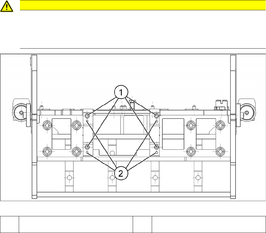
Installation
► Follow the removal instructions in reverse order for installation. Also observe the following instruc-
tions:
Installation position PCB camera (viewed from below)
CAUTION
Installation instructions
► Make sure you have the correct installation positions (see below)
► Replace any opened cable ties.
► Calibrate the PCB camera, the machine zero point and the head offset.
1 Installation position for C&P and Twin
heads
2 Installation position for DLM heads