00196497-07_SM_SXDX12_en.pdf - 第103页
Service Work Conveyor 3.4.14 Replacing the PCB Camera [03075363-xx] Gantries Service Manual SIPLACE SX1/SX2/DX1/DX2 FS02 103 Installation ► Follow the removal in structions in reverse order for installati o n. Also obser…
Service Work Conveyor
Gantries 3.4.14 Replacing the PCB Camera [03075363-xx]
102 Service Manual SIPLACE SX1/SX2/DX1/DX2 FS02
3.4.14
3.4.14 Replacing the PCB Camera [03075363-xx]
Replacing the PCB Camera [03075363-xx]
Parts, equipment and tools
▪ PCB camera (TYP34) 28 digital RK [03075363-xx] (standard)
▪ PCB camera (type 34HU) [03102921-xx] (for Twin VHF on 40mm gantry)
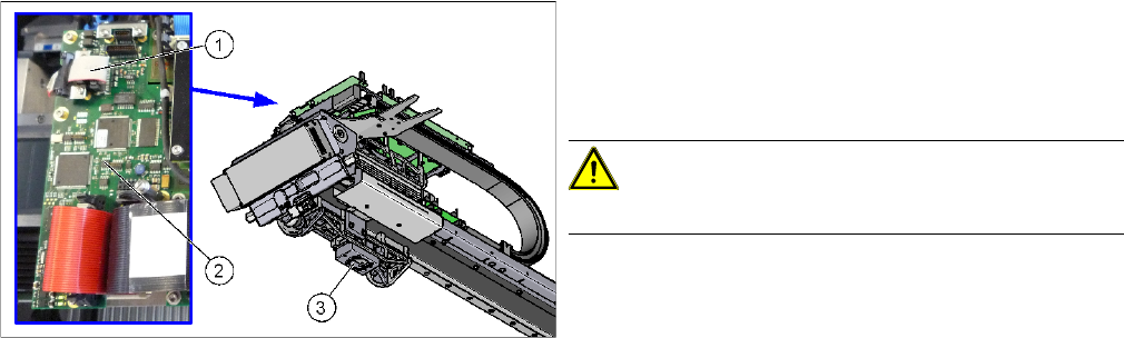
Overview
Removal
► Switch off the machine, disconnect it from the power supply and secure it to prevent unauthorized
reactivation. Observe the instructions in section "1.2 Preparatory Work..." [ ➙ 13].
► Unplug the PCB camera connector on the Vision board spread spectrum.
► Unplug the cable from the assembly plate. Open the corresponding cable ties to help you, if needed.
► Loosen the four screws fastening the PCB camera and remove it from the machine.
1. Connection of PCB camera to the Vision board
spread spectrum
2. Vision board spread spectrum
3. PCB camera
CAUTION!
Do not dismantle the PCB camera!
Service Work Conveyor
3.4.14 Replacing the PCB Camera [03075363-xx] Gantries
Service Manual SIPLACE SX1/SX2/DX1/DX2 FS02 103
Installation
► Follow the removal instructions in reverse order for installation. Also observe the following instruc-
tions:
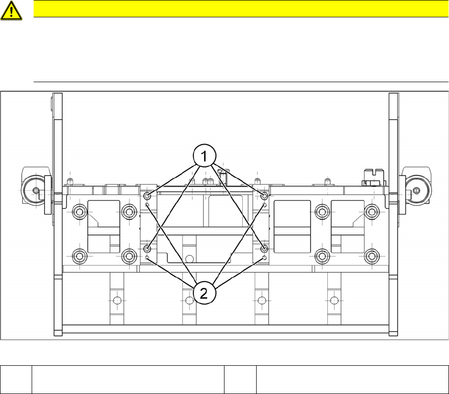
Installation position PCB camera (viewed from below)
CAUTION
Installation instructions
► Make sure you have the correct installation positions (see below)
► Replace any opened cable ties.
► Calibrate the PCB camera, the machine zero point and the head offset.
1 Installation position for C&P and Twin
heads
2 Installation position for DLM heads
Service Work Conveyor
Gantries 3.4.15 Replacing the MGCU/GCU
104 Service Manual SIPLACE SX1/SX2/DX1/DX2 FS02
3.4.15
3.4.15 Replacing the MGCU/GCU
Replacing the MGCU/GCU
Parts, Equipment and Tools
▪ Positioning control for the gantry axes GCU [03052200-xx]
or
MGCU [03117531-xx]
▪ If required, MGCU cable - X/Y motor cable extension
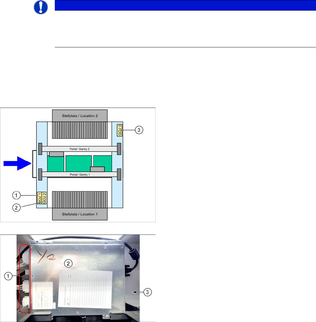
Overview
NOTICE
GCU or MGCU
GCU and MGCU are not compatible. A GCU must be replaced by a GCU and an MGCU must
be replaced by an MGCU.
MGCU are used in machines from serial no.: N001 upwards.
There is one MGCU/GCU available in the machine for
each of the following areas:
1. MCGU/GCU 1
Controls the Y axes (two linear drives) on gantry 1.
2. MGCU/GCU 2
Controls the X axes on gantry 1 and 2.
3. MGCU/GCU 3
Controls the Y axes (two linear drives) on gantry 2
(where present).
GCU
1. Connectors
2. GCU
3. Mount (bracket) at the back