00196497-07_SM_SXDX12_en.pdf - 第104页
Service Work Conveyor Gantries 3.4.15 Replacing the MGCU/GCU 104 Service Manual SIPLACE SX1/SX2/DX1/DX2 FS02 3.4.15 3 . 4 . 1 5 R e p la c in g t h e M G C U / G C U Replacing the MGCU/GCU Parts, Equipment and Tools ▪ Po…
Service Work Conveyor
3.4.14 Replacing the PCB Camera [03075363-xx] Gantries
Service Manual SIPLACE SX1/SX2/DX1/DX2 FS02 103
Installation
► Follow the removal instructions in reverse order for installation. Also observe the following instruc-
tions:
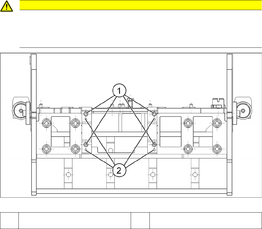
Installation position PCB camera (viewed from below)
CAUTION
Installation instructions
► Make sure you have the correct installation positions (see below)
► Replace any opened cable ties.
► Calibrate the PCB camera, the machine zero point and the head offset.
1 Installation position for C&P and Twin
heads
2 Installation position for DLM heads
Service Work Conveyor
Gantries 3.4.15 Replacing the MGCU/GCU
104 Service Manual SIPLACE SX1/SX2/DX1/DX2 FS02
3.4.15
3.4.15 Replacing the MGCU/GCU
Replacing the MGCU/GCU
Parts, Equipment and Tools
▪ Positioning control for the gantry axes GCU [03052200-xx]
or
MGCU [03117531-xx]
▪ If required, MGCU cable - X/Y motor cable extension
Overview
NOTICE
GCU or MGCU
GCU and MGCU are not compatible. A GCU must be replaced by a GCU and an MGCU must
be replaced by an MGCU.
MGCU are used in machines from serial no.: N001 upwards.
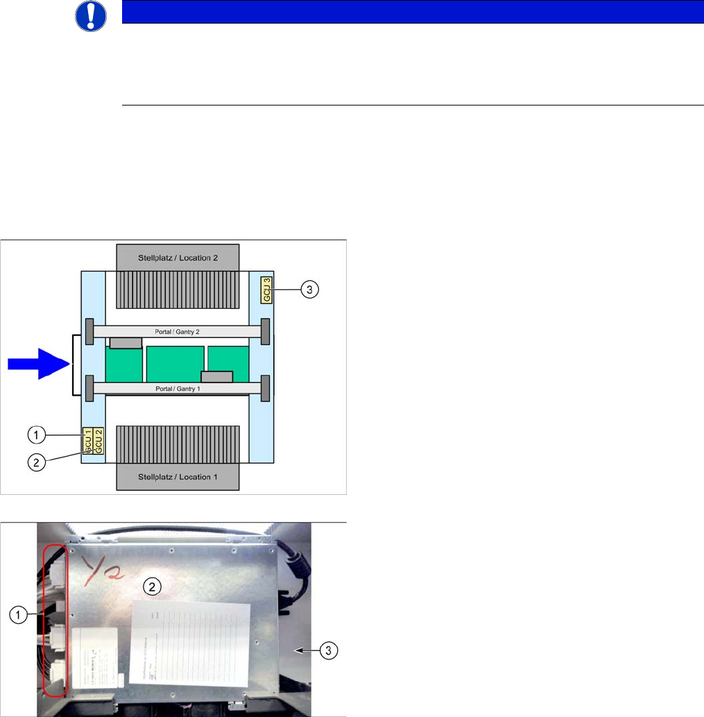
There is one MGCU/GCU available in the machine for
each of the following areas:
1. MCGU/GCU 1
Controls the Y axes (two linear drives) on gantry 1.
2. MGCU/GCU 2
Controls the X axes on gantry 1 and 2.
3. MGCU/GCU 3
Controls the Y axes (two linear drives) on gantry 2
(where present).
GCU
1. Connectors
2. GCU
3. Mount (bracket) at the back
Service Work Conveyor
3.4.15 Replacing the MGCU/GCU Gantries
Service Manual SIPLACE SX1/SX2/DX1/DX2 FS02 105
Removal
► Take a note of the component counter reading at the software user interface.
► Switch off the machine, disconnect it from the power supply and secure it to prevent unauthorized
reactivation. Observe the instructions in section "1.2 Preparatory Work..." [ ➙ 13].
► Unplug all connections on the MGCU/GCU. You may want to mark their positions, to make clear as-
signment easier later on.
► Remove the two fastening screws and lift off the mount.
► Remove the MGCU/GCU from the machine.
Installation
► Follow the removal instructions in reverse order for installation. Also observe the following instruc-
tions:
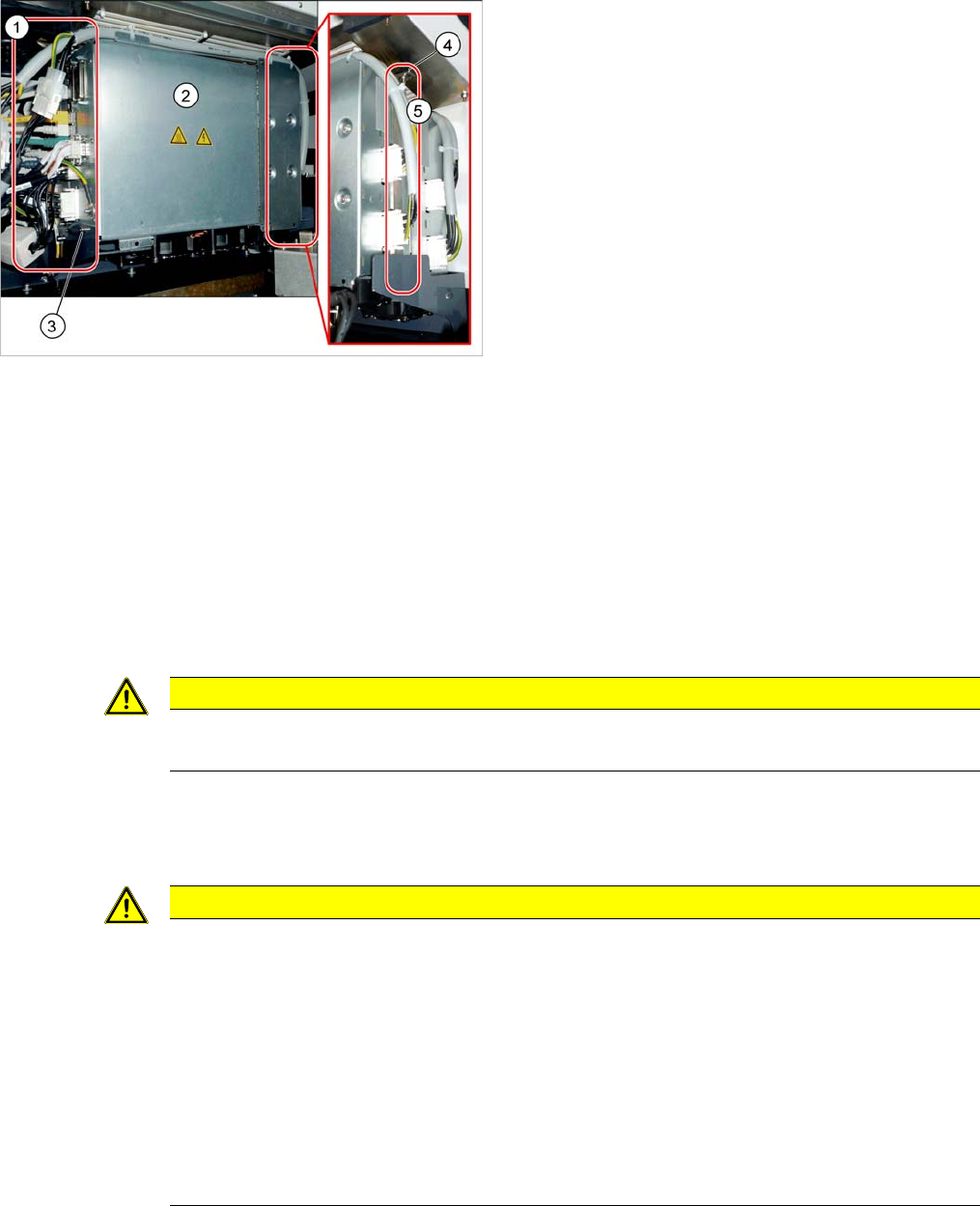
MGCU
1. Connectors
2. MGCU
3. Fastening screw at the bottom
4. Fastening screws on the mount
5. Mount (bracket) at the back
CAUTION
Magnets
Make sure that you do not move the MGCU/GCU too near to the magnets.
CAUTION
Installation instructions
► If required, the following parts from the old MGCU/GCU must be reused on the new one:
⇨ Cable (observe the orientation)
⇨ Mount
► Use the DIP switch to set the gantry ID on the MGCU/GCU (see "4.4.4 GCU (Up to Machine
Nos.: Mxxx)" [ ➙ 269]).
► Check the firmware and perform a download, if needed. (see "4.9.1 Firmware Download
(SW 70x)" [ ➙ 293]).
► Check the component counter reading. Please contact your SIPLACE Service team if you
have any problems with this.