00196497-07_SM_SXDX12_en.pdf - 第110页
Service Work Conveyor Gantries 3.4.16 Replacing the X Trailing Cable Vacuum [0 3075585-xx] 110 Service Manual SIPLACE SX1/SX2/DX1/DX2 FS02 ► Assemble the Vision board sp read spectrum in reve rse order and reco nnect the…
Service Work Conveyor
3.4.16 Replacing the X Trailing Cable Vacuum [03075585-xx] Gantries
Service Manual SIPLACE SX1/SX2/DX1/DX2 FS02 109
Points to be secured with Loctite 241
► Having loosened the screws indicated in the graphic, apply some Loctite 241 to the M4 threads and
retighten the screws.
► Replace the new trailing cable and fix it with the top
and bottom hexagon bolts. Do not forget the plates.
Carefully thread the flat ribbon cable through the
opening on the board holder. Make sure not to dam-
age the cables.
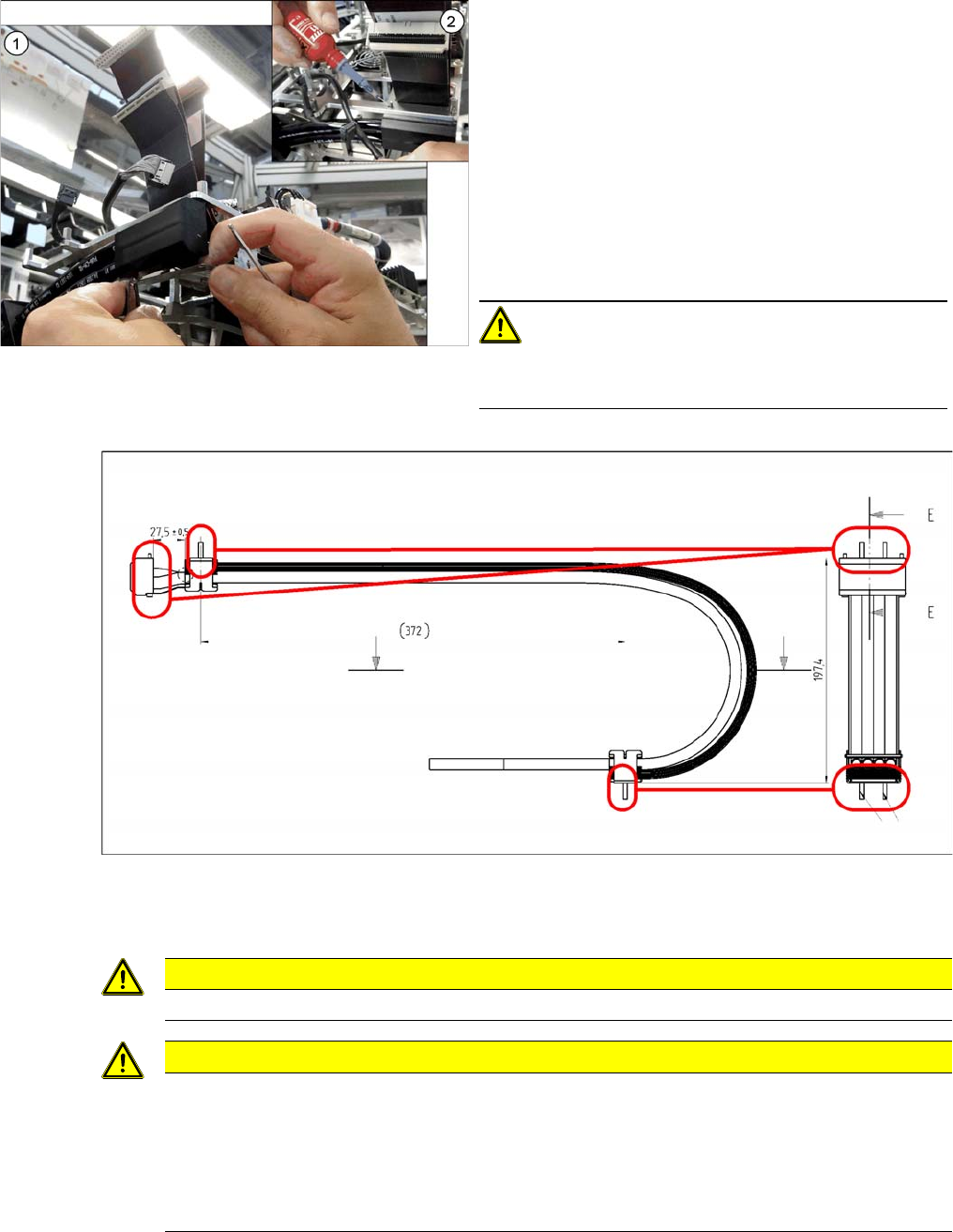
► (1) Fasten the vacuum distributor and the vacuum
connection. Use the two screws ISO4762-M3x40-
A2-70 [03043115-xx] and the shim plates DIN7985-
M3x3-A2-Z [00368583-xx] for the vacuum connec-
tion. Screw the mounting plate and the vacuum con-
nection to the board holder. Secure the screws of the
vacuum distributor with Loctite 241 (2).
CAUTION!
There are M3 press-in nuts on the head mount.
Press the screws against the nuts with only a little force.
CAUTION
Observe the current Loctite 241 safety data sheet by all means!
CAUTION
Leaky connection
The four-fold air supply hose cannot be glued in place until the trailing cable and the distributor
on the board holder have been assembled. Otherwise the connection could be damaged and
become leaky.
► For this reason, never open the hexagon bolts and the screws of the vacuum connection
on the top trailing cable if this is not absolutely necessary.
Service Work Conveyor
Gantries 3.4.16 Replacing the X Trailing Cable Vacuum [03075585-xx]
110 Service Manual SIPLACE SX1/SX2/DX1/DX2 FS02
► Assemble the Vision board spread spectrum in reverse order and reconnect the cables for compo-
nent camera, PCB camera and CAN bus. Also assemble the corresponding cable holders. (See also
"3.4.9 Replacing the Vision Board Spread Spectrum HCU [03067289-xx]" [ ➙ 94])
► Plug the flat ribbon cables of the trailing cable into the Vision board spread spectrum and the head
interface.
► Reconnect the hoses for the head to the vacuum distributor.
► Reconnect all electrical connections of the trailing cable to the gantry interface X. (See also "3.4.4
Replacing the Gantry InterfaceX [03065078‑xx]" [ ➙ 88])
See also
3.4.5 Replacing the Gantry InterfaceY [03065335‑xx] [ ➙ 90]
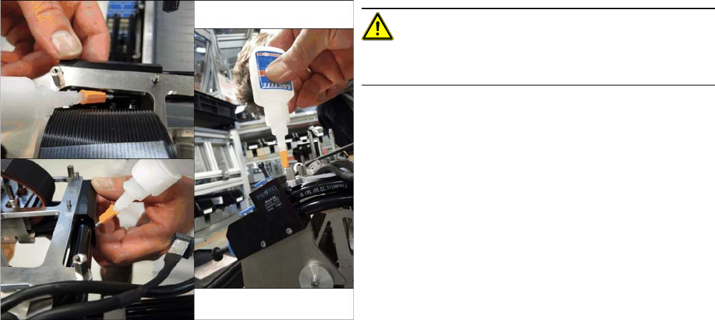
CAUTION!
Observe the current Loctite 406 safety data sheet by all
means!
► The hoses of the trailing cable must be secured with
the thin fluid Loctite 406 instant adhesive in the dis-
tributors.
Please use the dosage tip supplied. Make sure that a
thin adhesive film is laying around the hose. For this,
apply the adhesive directly on the interface between
distributor and hose. The adhesive is drawn into the
gap between hose and distributor by means of capil-
lary attraction.
Repeat this procedure for each individual hose as
well as for the four-fold air supply hose from the trail-
ing cable into the vacuum connection.
Service Work Conveyor
3.4.17 Replacing the Y Trailing Cable [03075584-xx] Gantries
Service Manual SIPLACE SX1/SX2/DX1/DX2 FS02 111
3.4.17
3.4.17 Replacing the Y Trailing Cable [03075584-xx]
Replacing the Y Trailing Cable [03075584-xx]
Parts, equipment and tools
▪ GR Y trailing cable vacuum assembly [03075584-xx]
Overview
Removal
► Switch off the machine, disconnect it from the power supply and secure it to prevent unauthorized
reactivation. Observe the instructions in section "1.2 Preparatory Work..." [ ➙ 13].
► Remove the cover over the gantry interface on the X and Y axes.
NOTICE
Repairing the hose
If the SX1, SX2, DX1 or DX2 hoses for the Y trailing cable break or become leaky, there is a
quick temporary repair solution. This enables you, for example, to continue production until the
spare part arrives and avoid unscheduled machine standstill.
Leakiness is indicated by loud whistling noises being emitted by the trailing cable.
The described repair solution is only available for the "GR Y trailing cable vacuum assembly"
[03075584-xx].
Provided they are not damaged, hoses 2 and 3 are used to repair the Y trailing cable.
► For more details, read the technical information "Repairing the Y Trailing Cable Hose" [DE:
TI2013-08D04] [EN: TI2013-08E04].
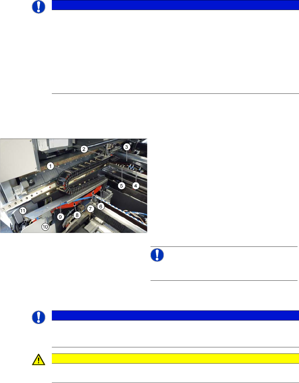
1. Trailing cable chain
2. Screws fastening the trailing cable chain to the gantry
3. Pneumatic hoses to the gantry
4. Gantry interface X
5. Gantry interface Y
6. Screws fastening the trailing cable chain to the cover
plate
7. Rear screw fastening the cover plate
8. Front screw fastening the cover plate
9. Cover plate
10. Valve terminal
11. Trailing interface
NOTICE!
For clarity, the cover on (3) to (5) in the diagram has al-
ready been removed
NOTICE
Marking the positions
► Before you unplug electrical or pneumatic connections, mark their positions, to make clear
assignment easier later on.
CAUTION
Cables and hoses
► Make sure that the trailing cable chain, cable and hoses are not folded or damaged.