00196497-07_SM_SXDX12_en.pdf - 第112页
Service Work Conveyor Gantries 3.4.17 Replacing the Y Trailing Cable [03075584-xx] 112 Service Manual SIPLACE SX1/SX2/DX1/DX2 FS02 ► Unplug all pneumatic connections to the gantry. ► Unplug all electrical connections fro…
Service Work Conveyor
3.4.17 Replacing the Y Trailing Cable [03075584-xx] Gantries
Service Manual SIPLACE SX1/SX2/DX1/DX2 FS02 111
3.4.17
3.4.17 Replacing the Y Trailing Cable [03075584-xx]
Replacing the Y Trailing Cable [03075584-xx]
Parts, equipment and tools
▪ GR Y trailing cable vacuum assembly [03075584-xx]
Overview
Removal
► Switch off the machine, disconnect it from the power supply and secure it to prevent unauthorized
reactivation. Observe the instructions in section "1.2 Preparatory Work..." [ ➙ 13].
► Remove the cover over the gantry interface on the X and Y axes.
NOTICE
Repairing the hose
If the SX1, SX2, DX1 or DX2 hoses for the Y trailing cable break or become leaky, there is a
quick temporary repair solution. This enables you, for example, to continue production until the
spare part arrives and avoid unscheduled machine standstill.
Leakiness is indicated by loud whistling noises being emitted by the trailing cable.
The described repair solution is only available for the "GR Y trailing cable vacuum assembly"
[03075584-xx].
Provided they are not damaged, hoses 2 and 3 are used to repair the Y trailing cable.
► For more details, read the technical information "Repairing the Y Trailing Cable Hose" [DE:
TI2013-08D04] [EN: TI2013-08E04].
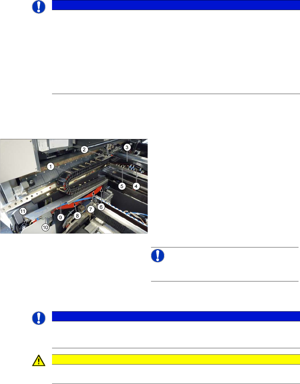
1. Trailing cable chain
2. Screws fastening the trailing cable chain to the gantry
3. Pneumatic hoses to the gantry
4. Gantry interface X
5. Gantry interface Y
6. Screws fastening the trailing cable chain to the cover
plate
7. Rear screw fastening the cover plate
8. Front screw fastening the cover plate
9. Cover plate
10. Valve terminal
11. Trailing interface
NOTICE!
For clarity, the cover on (3) to (5) in the diagram has al-
ready been removed
NOTICE
Marking the positions
► Before you unplug electrical or pneumatic connections, mark their positions, to make clear
assignment easier later on.
CAUTION
Cables and hoses
► Make sure that the trailing cable chain, cable and hoses are not folded or damaged.
Service Work Conveyor
Gantries 3.4.17 Replacing the Y Trailing Cable [03075584-xx]
112 Service Manual SIPLACE SX1/SX2/DX1/DX2 FS02
► Unplug all pneumatic connections to the gantry.
► Unplug all electrical connections from the trailing cable to the X and Y trailing cable interface. (See
also "3.4.4 Replacing the Gantry InterfaceX [03065078‑xx]" [➙88] and "3.4.5 Replacing the Gantry
InterfaceY [03065335‑xx]" [ ➙ 90])
► Unplug all pneumatic connections to the valve block.
► Unplug the electrical connections to the trailing cable interface. (See also "3.4.11 Replacing the Trail-
ing Cable Interface [03064127-xx]" [ ➙ 97])
► Loosen the two screws fastening the trailing cable chain to the gantry. These screws (hexagonal
bolts [03023606-xx]) must be resealed with Loctite 241 when fitted again.
► Loosen the front screw fastening the cover plate.
► Loosen the rear screw fastening the cover plate. There is a slot here. You can now push the cover
plate and lift it off the screw.
► Loosen the two screws fastening the trailing cable chain to the cover plate. These screws (hexagonal
bolts [03023606-xx]) must be resealed with Loctite 241 when fitted again.
► Remove the trailing cable from the machine.
Installation
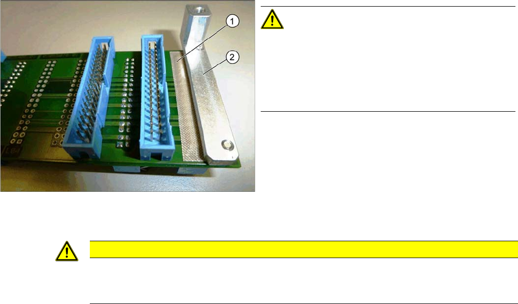
Adhesive Tape for Gantry Interface
► Follow the removal instructions in reverse order for installation. Also observe the following instruc-
tions:
CAUTION!
During assembly, make sure that the connection rail con-
tacts are insulated with adhesive tape (1) in the direction
of the aluminum holder (2). Do not use conductive tape,
recommendation [03000372-xx] "PTFE glass fiber mate-
rial, self-adhesive, width 20mm" for insulating the con-
tacts.
CAUTION
Installation instructions
► Fix the screws fastening the trailing cable chain to the gantry and to the cover with Loctite
241.
Service Work Conveyor
3.4.18 Replacing the X Axis Axial Fan [03056479-xx] Gantries
Service Manual SIPLACE SX1/SX2/DX1/DX2 FS02 113
3.4.18
3.4.18 Replacing the X Axis Axial Fan [03056479-xx]
Replacing the X Axis Axial Fan [03056479-xx]
Parts, equipment and tools
▪ Fan X/Y motor [03085456-xx]
▪ Locking varnish Loctite 241 [02101037-xx]
Overview
Removal
► Switch off the machine, disconnect it from the power supply and secure it to prevent unauthorized
reactivation. Observe the instructions in section "1.2 Preparatory Work..." [ ➙ 13].
► Dismantle the head adapter HCU. (See "3.4.20 Replacing the Head Adapter for the HCU and MHCU/
HCU" [ ➙ 115])
► Disconnect the fan from the power supply.
► Loosen the 4 screws fastening the fan and remove the fan.
Installation
► Follow the removal instructions in reverse order for installation. Also observe the following instruc-
tions:
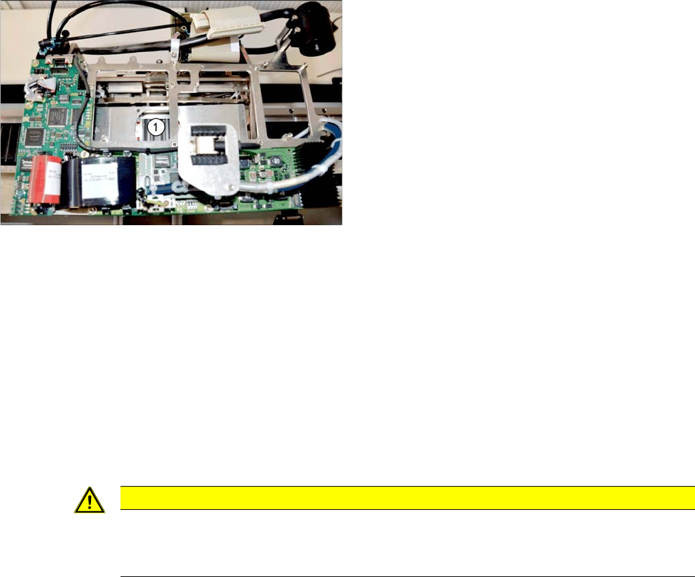
1. Installation point for X axis axial fan
CAUTION
Installation instructions
► Secure the fastening screws with Loctite 241.
► Replace any cable ties which you have removed.