00196497-07_SM_SXDX12_en.pdf - 第115页
Service Work Conveyor 3.4.20 Replacing the Head Adapter for the HCU and MHCU/HCU Gantr ies Service Manual SIPLACE SX1/SX2/DX1/DX2 FS02 115 3.4.20 3 . 4 . 2 0 R e p la c in g t h e H e a d A d a p t e r f o r t h e H C U …
Service Work Conveyor
Gantries 3.4.19 Replacing the Y Axis Axial Fan [03056479-xx]
114 Service Manual SIPLACE SX1/SX2/DX1/DX2 FS02
3.4.19
3.4.19 Replacing the Y Axis Axial Fan [03056479-xx]
Replacing the Y Axis Axial Fan [03056479-xx]
Parts, equipment and tools
▪ Fan X/Y motor [03085456-xx]
▪ Locking varnish Loctite 241 [02101037-xx]
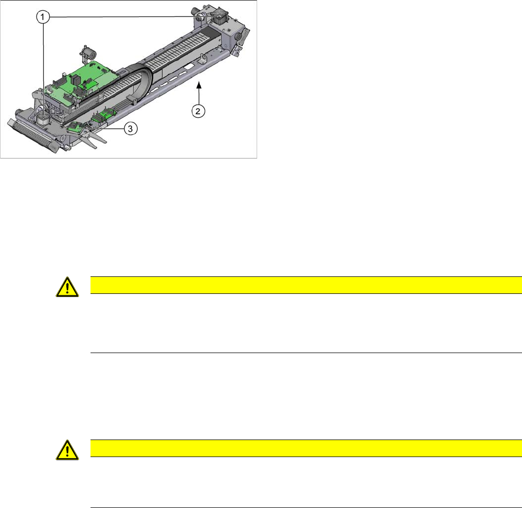
Overview
Removal
► Switch off the machine, disconnect it from the power supply and secure it to prevent unauthorized
reactivation. Observe the instructions in section "1.2 Preparatory Work..." [ ➙ 13].
► Loosen the connection cable of the fan. Depending on the gantry side, this is either fitted on the sen-
sor module Y or on the sensor interface. You may want to mark the position, to make clear assign-
ment easier later on.
► Loosen the 4 screws fastening the fan and remove the fan.
Installation
► Follow the removal instructions in reverse order for installation. Also observe the following instruc-
tions:
1. Axial fan Y axis on gantry
2. Sensor interface (on the underside of the gantry)
3. Sensor module Y
CAUTION
Do not pull on the cable!
► When disconnecting the cables from the sensor module Y, do not pull on the cable but only
on the black plastic connector. If you pull on the cable, this could damage the sensor mod-
ule.
CAUTION
Installation instructions
► Secure the fastening screws with Loctite 241.
► Replace any cable ties which you have removed.
Service Work Conveyor
3.4.20 Replacing the Head Adapter for the HCU and MHCU/HCU Gantries
Service Manual SIPLACE SX1/SX2/DX1/DX2 FS02 115
3.4.20
3.4.20 Replacing the Head Adapter for the HCU and MHCU/HCU
Replacing the Head Adapter for the HCU and MHCU/HCU
Parts, Equipment and Tools
The head adapter version needed depends on the head which is installed:
▪ Head adapter HCU for CPP and C&P20A [03065868-xx]
(consists of 1x PCB/B base adapter C&P [03055516-xx] and 1x HCU assembly [03054884-xx])
▪ Head adapter HCU for TwinHead [03065969-xx]
(consists of 1x PCB/B base adapter TWIN [03055517-xx] and 2x HCU assembly [03054884-xx])
▪ Head adapter HCU for VHF PP SX1/SX2 [03098389-xx]
(consists of 1x PCB/B base adapter TWIN [03055517-xx] and 2x HCU assembly [03054884-xx])
▪ MHCU assembly compatible [03090990-xx] from FS04 (replaces: HCU assembly [03054884-xx])
Overview
Removal
► Switch off the machine, disconnect it from the power supply and secure it to prevent unauthorized
reactivation. Observe the instructions in section "1.2 Preparatory Work..." [ ➙ 13].
► If there is a cover above the boards, dismantle it.
NOTICE
C&P20 P
The following additional conditions must be fulfilled for operating a C&P20 P:
► The base adapter needs at least function state -06.
► Make sure to use MHCU [03090990-xx].
► You find a complete list of the prerequisites in section Replacing the C&P20 P Head.
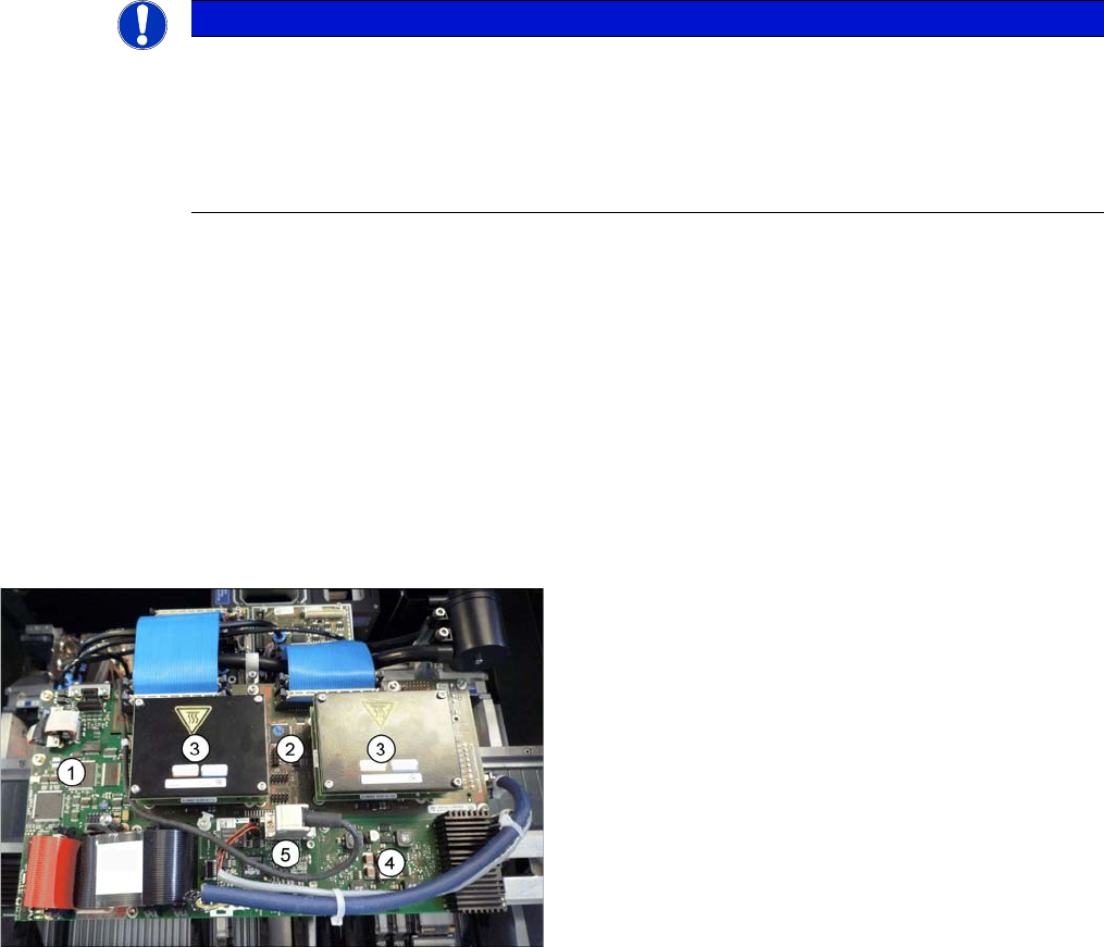
Boards on the Gantry
1. Vision board spread spectrum
2. Head adapter (here the version for the TwinHead with
2 HCUs)
3. HCU
4. Head interface
5. Sensor module
Service Work Conveyor
Gantries 3.4.20 Replacing the Head Adapter for the HCU and MHCU/HCU
116 Service Manual SIPLACE SX1/SX2/DX1/DX2 FS02
► If you have ordered the base adapter without HCU(s) you will have to convert the HCU(s).
Remove the two screws fastening the HCU on the underside of the board and carefully pull the HCU
off the base adapter. Make sure not to damage the pins located below. Repeat this procedure for the
second HCU, if necessary (for TwinHead only).
Installation
► Follow the removal instructions in reverse order for installation. Also observe the following instruc-
tions:
See also
5.2.5.2 Base adapter TWIN [03055517-xx] [ ➙ 319]
5.2.5.1 Base adapter C&P [03055516-xx] [ ➙ 317]
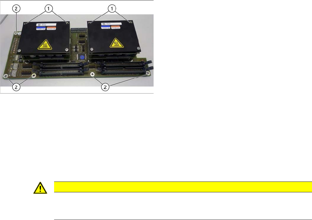
Head adapter HCU (here the TwinHead version)
► Unplug all electrical connections. You may want to
mark their positions, to make clear assignment easier
later on.
► Remove the two front screws (1) fastening the HCU
in each case. Make sure that you do not lose the
shims. Make a note of the number of washers used
for each screw, as this may well differ.
► Undo all the screws (2) fastening the board and then
remove the board.
CAUTION
Installation instructions
► Check the firmware and perform a download, if needed. (See "4.9.1 Firmware Download
(SW 70x)" [ ➙ 293])