00196497-07_SM_SXDX12_en.pdf - 第125页
Service Work Conveyor 3.5.3 Replacing the C&P20/A/M Head Placement heads Service Manual SIPLACE SX1/SX2/DX1/DX2 FS02 125 3.5.3 3 . 5 . 3 R e p la c in g t h e C & P 2 0 / A / M H e a d Replacing the C&P20/A/M…
Service Work Conveyor
Placement heads 3.5.2 Differentiation of the C&P20 Head Variants
124 Service Manual SIPLACE SX1/SX2/DX1/DX2 FS02
3.5.2
3.5.2 Differentiation of the C&P20 Head Variants
Differentiation of the C&P20 Head Variants
C&P20 Differentiation
Differentiation of the C&P20 head variants
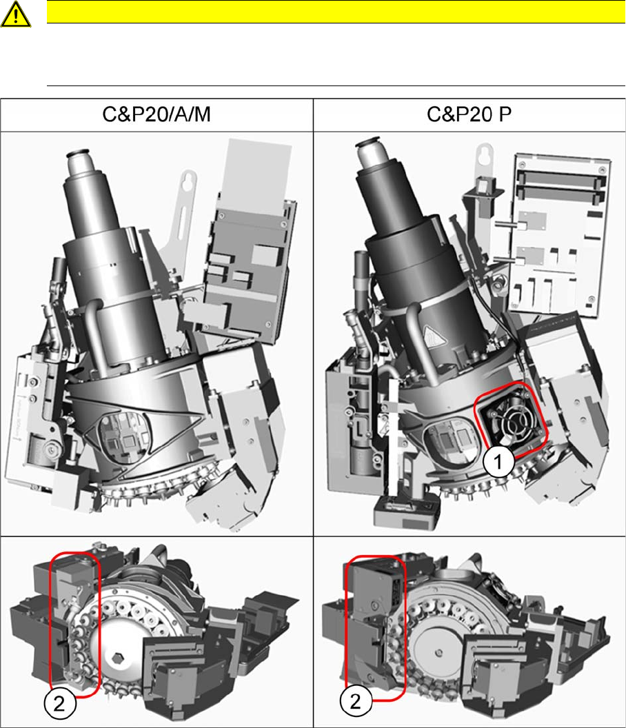
The C&P20/A/M and the C&P20 P head differ in many details. They are easily identified by the following
features:
1. The C&P20 P can be identified by the fan. This fan is not present on the C&P20/A/M heads.
2. The component sensor is flatter and wider on the C&P20 P than on the C&P20/A/M.
CAUTION
Do not confuse the different C&P20 head variants.
► Parts from the C&P20/A/M head can not usually be used for the C&P20 P head (and vice
versa)!

Service Work Conveyor
3.5.3 Replacing the C&P20/A/M Head Placement heads
Service Manual SIPLACE SX1/SX2/DX1/DX2 FS02 125
3.5.3
3.5.3 Replacing the C&P20/A/M Head
Replacing the C&P20/A/M Head
Complete contents; Replacing C&P20/A/M
Vacuum Test Before Removal
Parts, Equipment and Tools
▪ Select the placement head:
SXDX12V1V2 – No C&P20 M Heads
▪ Torque screwdriver 1-5 Nm [03078400-xx]
▪ Extension/straight TX20 [03073256-xx]
▪ Bit holder for Torque Vario-S screwdriver [03078706-xx]
▪ Torx Allen screwdriver TX8 [03080081-xx]
▪ Calibration tool version SST23 [03034148-xx]
▪ Protective hose for component sensor [03078596-xx]
▪ For additional work on the placement head:
Head assembly stand [03056231-xx]
Service manual "C&P20 / C&P20 A / C&P20 M head" [DE: 00197464-xx] [EN: 00197465-xx]
▪ For vacuum pump operation, if required:
- Assembly instructions "Vacuum pump X-Series S, SX4/DX4" [00196845-xx]
- Assembly instructions "Vacuum pump SX1/2, DX1/2" [00196614-xx]
- Assembly instructions "Vacuum pump X-Series (SC 70x)" [00196433-xx]
- Assembly instructions "Vacuum pump X-Series" [00195089-xx]
NOTICE
Vacuum test
► If required, perform a vacuum test before removing the placement head.
Read the "Service manual Vacuum test at C&P placement head" [DE+EN: 00196101-xx]
for this.
NOTICE
Fast Head Exchange (FHE)
► Observe the instructions in section "3.5.1 Fast Head Exchange" [➙119] when exchanging
a head.
NOTICE
Example
Replacement of the placement head is shown using the example of a C&P20 A machine. The
replacement procedure for other C&P20 placement heads is the same. Any differences will be
explicitly indicated.
Head type Camera Item no.
C&P20A With Camera SST23 03062095-xx
Without camera 03058420-xx
Service Work Conveyor
Placement heads 3.5.3 Replacing the C&P20/A/M Head
126 Service Manual SIPLACE SX1/SX2/DX1/DX2 FS02
Removal
► Switch off the machine, disconnect it from the power supply and secure it to prevent unauthorized
reactivation. Observe the instructions in section "1.2 Preparatory Work..." [ ➙ 13].
► Remove all four M4 fastening screws with a long Torx key.
► Carefully lift the head out of the locating pins on the head plate.
► If you need to perform further work on this head (e.g. replacing spare parts), fit the head to the head
mount [03056231-xx].
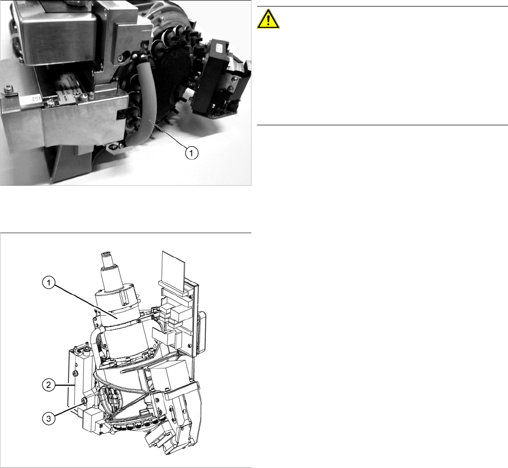
Hose on component sensor (example of C&P20 A
shown)
CAUTION!
The component sensor prisms, underneath the place-
ment head, are easily damaged. Take great care when
dismantling the head!
Protect the component sensor with a piece of hose (1).
This is delivered with the placement head or component
sensor and should be stored in the service box for the
machine, as it is required for dismantling the head.
► Disconnect the compressed air connection (1).
► Disconnect the flat ribbon cable from the placement
head.
► Remove the screws fastening the strain relief on the
component camera cables and carefully unplug the
cables. While unplugging the cables, press the
clamps on both sides of the connectors.
► Loosen the two screws on the pressure control valve
(2).
► Remove the screw (3) from the pressure control
valve and swing the pressure control valve to one
side.
The head fastening screw near the pressure control
valve is now accessible.