00196497-07_SM_SXDX12_en.pdf - 第13页
Introduction 1.1.8 Classification of the Optical Systems Preparatory Work... Service Manual SIPLACE SX1/SX2/DX1/DX2 FS02 13 1.2 1 . 2 P r e p a r a t o r y W o r k . . . Preparatory Work... Purpose and Scope Before perfo…
Introduction
Safety Instructions 1.1.8 Classification of the Optical Systems
12 Service Manual SIPLACE SX1/SX2/DX1/DX2 FS02
1.1.8
1.1.8 Classification of the Optical Systems
Classification of the Optical Systems
1.1.8.1
1.1.8.1 Classification of the Whole Machine
Classification of the Whole Machine
1.1.8.2
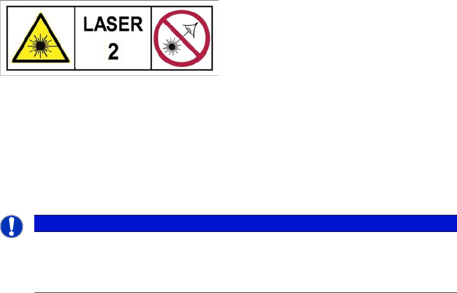
1.1.8.2 Laser Classification
Laser Classification
The following modules are assigned to the laser class 2:
▪ PCB barcode scanner
▪ Component sensor on the SpeedStar
▪ Component sensor on the MultiStar
▪ Laser light barriers at the board conveyor
1.1.8.3
1.1.8.3 Classification of the Camera Systems
Classification of the Camera Systems
The ready-to-operate overall machine is assigned to
laser class 2.
The laser classes are determined according to IEC
60825-1:2014.
NOTICE
LEDs
The camera illumination systems are fitted with light LEDs. These are assigned to risk group 1
according to IEC 62741:2006.
► Do not look into beam!
Introduction
1.1.8 Classification of the Optical Systems Preparatory Work...
Service Manual SIPLACE SX1/SX2/DX1/DX2 FS02 13
1.2
1.2 Preparatory Work...
Preparatory Work...
Purpose and Scope
Before performing any preventive maintenance work, conversion work or service work, a procedure of
locking and tagging must be followed and warning signs must be attached if not stated otherwise. If it is
not necessary to switch off the machine, it is explicitly mentioned.
The procedure, when followed correctly, eliminates the possibility of an employee being injured.
Description
Whenever it becomes necessary to isolate, control and release energy, the following procedure is to be
followed.
► Notify affected employees.
► Switch off the machine and all additional devices. Carry out all normal stopping procedures:
⇨ Press the STOP button.
⇨ Shut down the station computer.
⇨ Switch the machine off at the main switch.
► Isolate the machine from all its energy sources:
⇨ Shut off the compressed air supply.
⇨ Shut off the main power supply.
► Lock out the machine.
⇨ Attach a lock wherever possible (e.g. to the main power switch or the motor contactor).
NOTICE
Additional safety measures
These procedures represent the minimum lock/tag out requirements for the machine during
preventive maintenance work and service work. Any additional safeguards needed to complete
work safely can be specified by facilities supervision, the safety officer, the safety committee
and the health department.
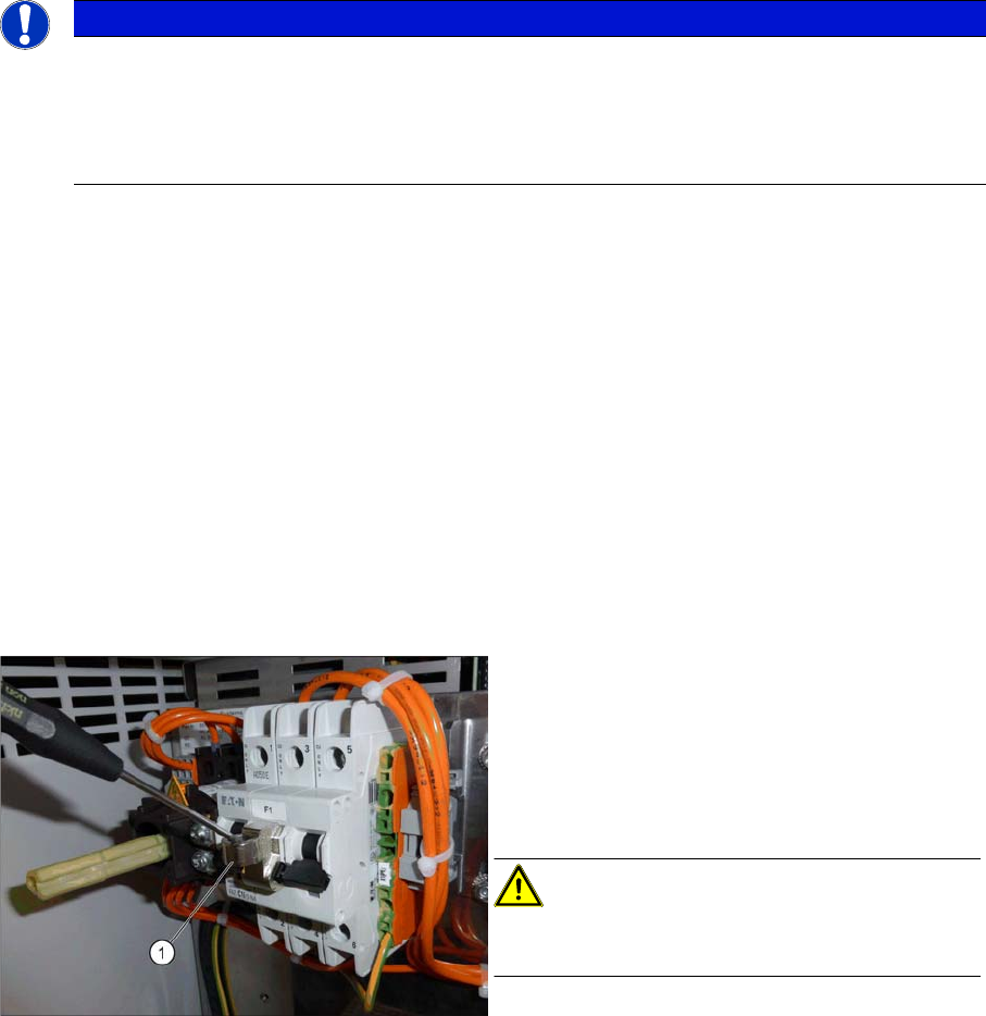
Attaching the lockout attachment [03121545-xx]
Example 1: Securing the machine with a lockout at-
tachment
The lockout attachment can prevent the machine
from being switched on inadvertently.
► Switch off the machine.
► Set the circuit breaker to OFF.
CAUTION!
The lockout attachment may only be attached when
the machine is switched off!
► Attach the lockout attachment (1) to the circuit
breaker.
► Secure the circuit breaker with a padlock.
Introduction
Preparatory Work... 1.1.8 Classification of the Optical Systems
14 Service Manual SIPLACE SX1/SX2/DX1/DX2 FS02
Lockout attachment [03121545-xx]
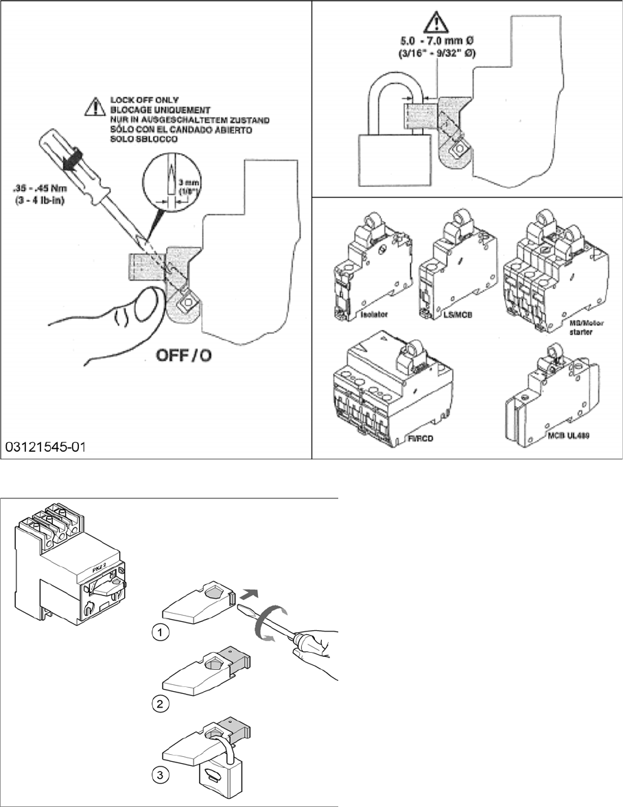
Attaching a padlock to the motor contactor
Example 2: Attaching a padlock to the motor
contactor
► Turn the operating lever (1) counterclock-
wise.
► Use the screwdriver to push the locking
lug (2) out of the operating lever (1).
► Secure the operating lever with a padlock
(3).