00196497-07_SM_SXDX12_en.pdf - 第136页
Service Work Conveyor Placement heads 3.5.6 Replacing the DLM4 Head 136 Service Manual SIPLACE SX1/SX2/DX1/DX2 FS02 Removal ► If possible, use calibration nozzles of type 3056 [00330538-xx] (with the help of the station …
Service Work Conveyor
3.5.6 Replacing the DLM4 Head Placement heads
Service Manual SIPLACE SX1/SX2/DX1/DX2 FS02 135
3.5.6
3.5.6 Replacing the DLM4 Head
Replacing the DLM4 Head
Parts, Equipment and Tools
▪ DLM4 head with 12 segments (without sleeves) [03082533-xx]
▪ Adapter plate assembly DLM4-DX1/2 [03082158-xx], if necessary
▪ Torque screwdriver 1-5 Nm [03078400-xx]
▪ Extension/straight TX20 [03073256-xx]
▪ Bit holder for Torque Vario-S screwdriver [03078706-xx]
▪ Extension/straight [03043440-xx]
▪ Extension / with joint [03042635-xx]
▪ Torx Allen screwdriver TX8 [03080081-xx]
▪ Calibration tool version 3 [03010565-xx]
▪ 12x calibration nozzles type 3056 [00330538-xx]
▪ For additional work on the placement head:
Head assembly stand [03056231-xx]
Service manual "DLM3/DLM4/DLM head" [DE: 00197466-xx] [EN: 00197467-xx]
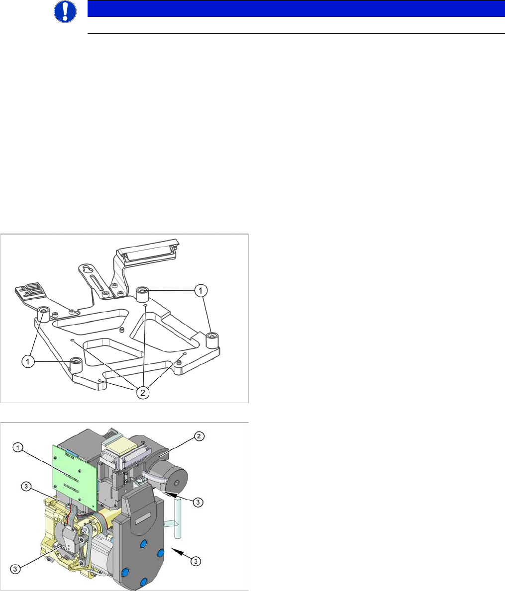
Overview
NOTICE
The adapter plate is only needed for the DLM4 heads.
Adapter plate assembly DLM4-DX1/2 [03082158-xx]
1. Fastening screws for the adapter plate on the head
plate
2. Fastening screws for the DLM head on the adapter
plate
1. Illumination control
2. Vacuum generator
3. Four fastening screws M4x18 on the adapter plate
Service Work Conveyor
Placement heads 3.5.6 Replacing the DLM4 Head
136 Service Manual SIPLACE SX1/SX2/DX1/DX2 FS02
Removal
► If possible, use calibration nozzles of type 3056 [00330538-xx] (with the help of the station software).
► Switch off the machine, disconnect it from the power supply and secure it to prevent unauthorized
reactivation. Observe the instructions in section "1.2 Preparatory Work..." [ ➙ 13].
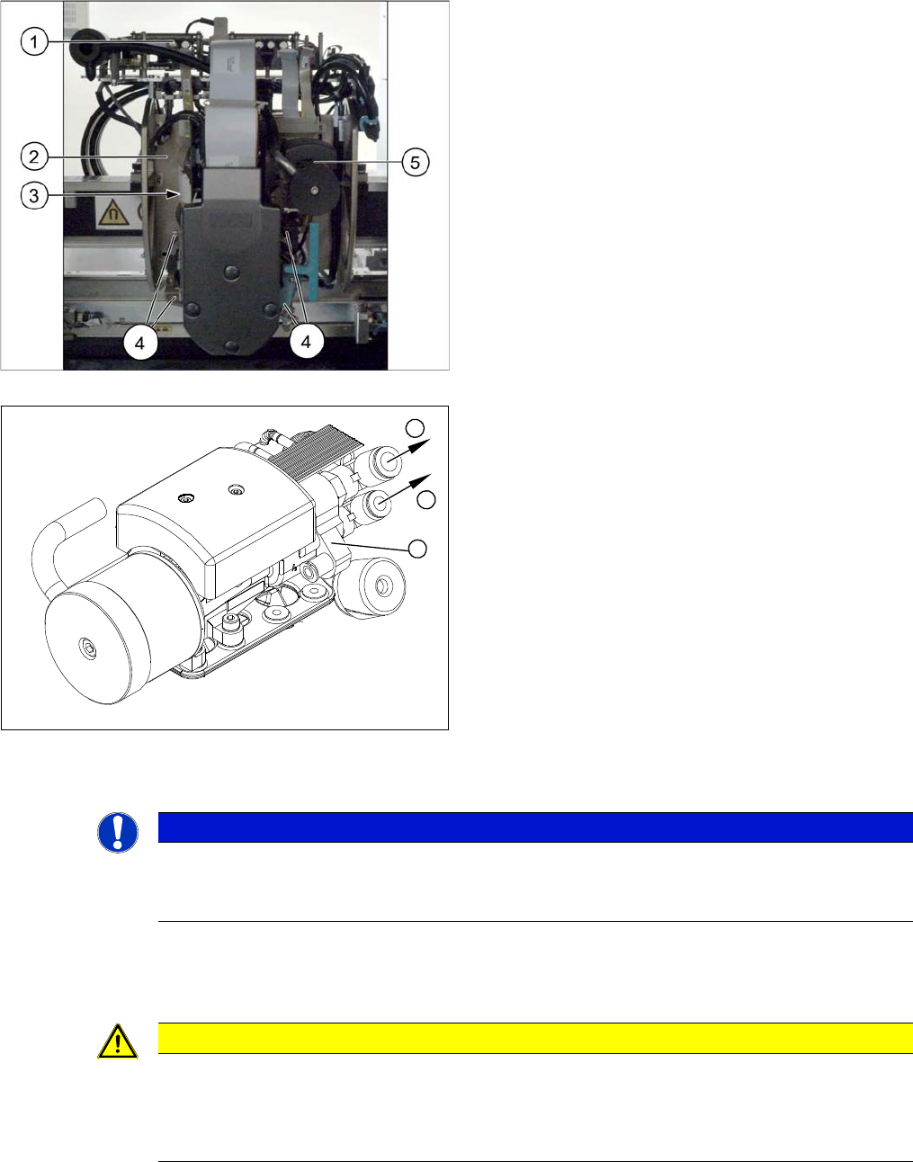
1. Head interface and head adapter
2. Head plate
3. Adapter plate (between head plate and head)
4. Screws fastening the head to the adapter plate
5. Vacuum generator
1. Compressed air hoses
2. Vacuum generator
1
1
2
NOTICE
Marking the connections
Before you unplug electrical or pneumatic connections, mark their positions, to make clear as-
signment easier later on.
CAUTION
Do not place the head down on the valve positioning drives!
The valve positioning drives of the star can be misaligned under mechanical loads.
► After removal, place the head carefully down on a soft surface, without putting pressure on
the valve positioning drives.
Service Work Conveyor
3.5.6 Replacing the DLM4 Head Placement heads
Service Manual SIPLACE SX1/SX2/DX1/DX2 FS02 137
► Remove the compressed air hoses from the pneumatic coupling of the vacuum generator.
► At the head, unplug the press-fit connections to the head interface and head adapter.
► Loosen the four undetachable fastening screws (M4x18) on the adapter plate.
The head is now hanging on the safety hook of the head mount, together with the adapter plate.
► From the front, take the head off the pins and safety hook.
► Place the head down on the adapter plate.
► Undo the four screws fastening the camera and then remove the camera.
► Remove all sleeves.
► Undo the four screws fastening the adapter plate and then remove the adapter plate.
► If you need to perform further work on this head (e.g. replacing spare parts), fit the head to the head
mount [03056231-xx].
Installation
The head is delivered without a camera, sleeves or adapter plate. These need to be installed from the
old head, as part of a spare parts changeover.
► Place the head on the adapter plate and screw it tight. Make sure that the parallel pins on the adapter
plate slide into the holes drilled into the back part of the head.
► Fix the camera in place with the four screws.
► Unplug the camera cable from the base adapter.
► Insert all sleeves with calibration nozzles of type 3056 [00330538-xx].
► Hook the head with the adapter plate onto the safety hook of the head plate.
► Carefully push the head towards the head plate until it slides onto the cylinder pins and lies flat
against the head plate.
► Fix the head and adapter plate to the head plate with the four screws.
► Connect the compressed air hoses to the pneumatic coupling on the vacuum generator.
► Reconnect to the electricity system.
► Calibrate the head with the help of the station software.
See also
3.5.7 Installation Positions on the Head Plate [ ➙ 138]
4.9.2 Calibration [ ➙ 294]
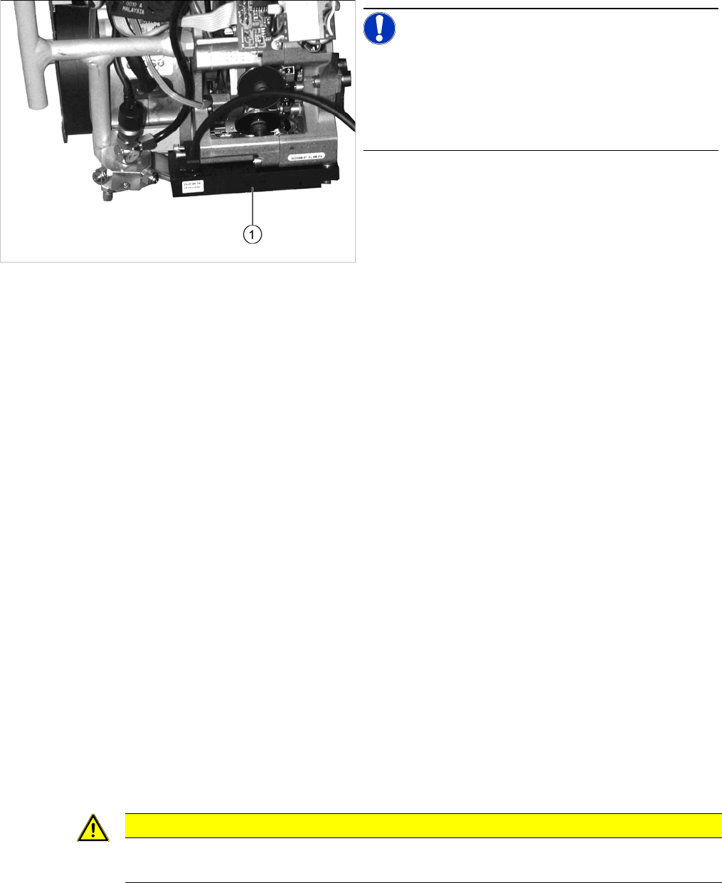
NOTICE!
The component sensor is optional.
If a component sensor (1) is available, undo the two fas-
tening screws and remove the head.
The DLM4 head does not support the component sensor;
for this reason it is missing.
CAUTION
Observe the torque
The screws fastening the adapter plate and the head must be tightened with a torque of 2.7 Nm.