00196497-07_SM_SXDX12_en.pdf - 第141页
Service Work Conveyor 3.5.8 Replacing Stationary Co mponent Camera Digital Type 25/33/ 36 Placement heads Service Manual SIPLACE SX1/SX2/DX1/DX2 FS02 141 Stationary Camera in Position 3 1. Screw 2. Thread in the mach ine…
Service Work Conveyor
Placement heads 3.5.8 Replacing Stationary Component Camera Digital Type 25/33/36
140 Service Manual SIPLACE SX1/SX2/DX1/DX2 FS02
3.5.8
3.5.8 Replacing Stationary Component Camera Digital Type 25/33/36
Replacing Stationary Component Camera Digital Type 25/33/36
Refer to the appropriate assembly instructions:
Stationary Camera X Series, SX Series, D3, and D1:
X Series, SX Series, D3, and D1:
▪ Assembly Instructions Stationary Camera 25 (FC) [00194554-xx] (German and English)
▪ Assembly Instructions Stationary Camera Type 33/36 (IC) [00196608-xx] (German and English)
See also
4.9.4 DIP Switch for Camera Types 25 and 33 [ ➙ 297]
3.5.8.1
3.5.8.1 Installation Height of the Stationary Camera
Installation Height of the Stationary Camera
The installation height at which the camera can be installed depends on the camera version. You will
either only be able to use one specific height or will have the option of several installation heights. The
following description only applies for the following camera versions with three possible installation
heights:
▪ Stationary component camera P&P (type 33) 55x45 digit. [03016339-xx] from version -06
▪ Stationary component camera P&P (type 36) 32x32 digit. [03042491-xx] from version -04
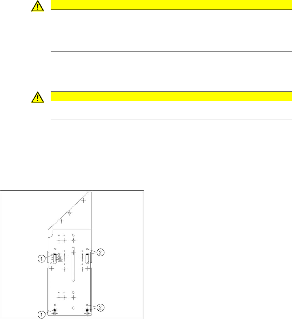
Stationary Camera in Position 1
Stationary Camera in Position 2
Position 2 is not relevant for the SX and the X series.
CAUTION
Risk of injury with cameras of type 25
A heavy mark caul is mounted with the same fixture screws for cameras of type 25. This mark
caul is otherwise only held by the locating pins. If this mark caul falls down, it could cause inju-
ries.
► Make sure that this mark caul is not pulled off the locating pins.
CAUTION
Head crash danger
An incorrect installation height can result in a head crash!
1. Screw
2. Thread in the machine frame
Position 1 has to be used in the following cases:
▪ SX1/SX2: always
▪ SX4, X series: If at least one DLM or CPP head is
used in the corresponding placement area.
Service Work Conveyor
3.5.8 Replacing Stationary Component Camera Digital Type 25/33/36 Placement heads
Service Manual SIPLACE SX1/SX2/DX1/DX2 FS02 141
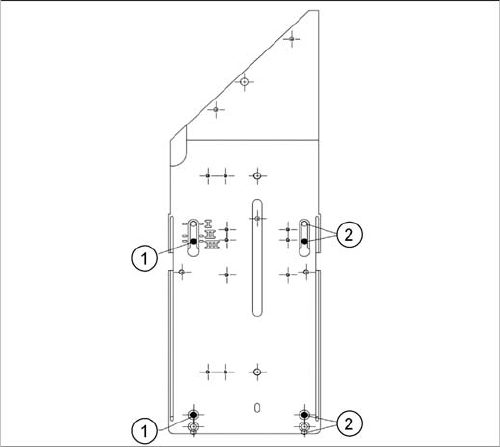
Stationary Camera in Position 3
1. Screw
2. Thread in the machine frame
Position 3 has to be used in the following cases:
▪ SX1/SX2: never.
▪ SX4, X series: If only TwinHeads are used in the cor-
responding placement area.

Service Work Conveyor
Conveyor 3.5.8 Replacing Stationary Component Camera Digital Type 25/33/36
142 Service Manual SIPLACE SX1/SX2/DX1/DX2 FS02
3.6
3.6 Conveyor
Conveyor
Conveyo r X-Series S, SX-Ser ies, DX-S eries – Ca ution: Moving the Conveyor Sides
CAUTION
Moving the conveyor sides
The conveyor sides are highly sensitive and may not be moved unless you have released the
brakes. If you do move them without releasing the brakes, this could cause irreparable damage
to the conveyor sides.
► We recommend that you use the software to help you move the conveyor sides.
► If you are not able to do this, the conveyor sides of dual conveyors can also be moved by
manually docking in the adjustment units. Make sure that the cylinders in all clamping units
of a particular side engage. The conveyor sides can then be moved by carefully pulling on
the toothed belt of the width adjustment unit.
► If you are not able to do this, the brakes of dual conveyors can also be manually released
using a pin. Take special care not to distort the conveyor sides.
NOTICE
New conveyor since 09/2011
There are various versions of the PCB conveyor. This manual refers to the function states 01
and 02.
► For machines of type SX1/SX2 V2, with conveyor SX V2, please refer to the service manual
"SIPLACE SX1/SX2 V2" [00196999-xx].