00196497-07_SM_SXDX12_en.pdf - 第142页
Service Work Conveyor Conveyor 3.5.8 Replacing Stationary Component Camera Dig ital Typ e 25/33/36 142 Service Manual SIPLACE SX1/SX2/DX1/DX2 FS02 3.6 3 . 6 C o n v e y o r Conveyor Conveyo r X-Series S, SX-Ser ies, DX-S…
Service Work Conveyor
3.5.8 Replacing Stationary Component Camera Digital Type 25/33/36 Placement heads
Service Manual SIPLACE SX1/SX2/DX1/DX2 FS02 141
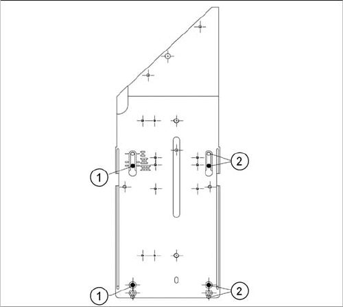
Stationary Camera in Position 3
1. Screw
2. Thread in the machine frame
Position 3 has to be used in the following cases:
▪ SX1/SX2: never.
▪ SX4, X series: If only TwinHeads are used in the cor-
responding placement area.

Service Work Conveyor
Conveyor 3.5.8 Replacing Stationary Component Camera Digital Type 25/33/36
142 Service Manual SIPLACE SX1/SX2/DX1/DX2 FS02
3.6
3.6 Conveyor
Conveyor
Conveyo r X-Series S, SX-Ser ies, DX-S eries – Ca ution: Moving the Conveyor Sides
CAUTION
Moving the conveyor sides
The conveyor sides are highly sensitive and may not be moved unless you have released the
brakes. If you do move them without releasing the brakes, this could cause irreparable damage
to the conveyor sides.
► We recommend that you use the software to help you move the conveyor sides.
► If you are not able to do this, the conveyor sides of dual conveyors can also be moved by
manually docking in the adjustment units. Make sure that the cylinders in all clamping units
of a particular side engage. The conveyor sides can then be moved by carefully pulling on
the toothed belt of the width adjustment unit.
► If you are not able to do this, the brakes of dual conveyors can also be manually released
using a pin. Take special care not to distort the conveyor sides.
NOTICE
New conveyor since 09/2011
There are various versions of the PCB conveyor. This manual refers to the function states 01
and 02.
► For machines of type SX1/SX2 V2, with conveyor SX V2, please refer to the service manual
"SIPLACE SX1/SX2 V2" [00196999-xx].
Service Work Conveyor
3.6.1 Loosening the Conveyor Side Clamps Conveyor
Service Manual SIPLACE SX1/SX2/DX1/DX2 FS02 143
3.6.1
3.6.1 Loosening the Conveyor Side Clamps
Loosening the Conveyor Side Clamps
Many tasks performed on the conveyor require that the conveyor sides are moved when the machine is
switched off. The clamps on the conveyor sides of dual conveyors can be released for this.
0100 - SXDX12V1V2 SXDX4 X34iS
Conveyo r X-Series S, SX-Ser ies, DX-S eries – Ca ution: Moving the Conveyor Sides
See also
4.6.3.1 Setting the Fixed Conveyor Side on Single Conveyors [ ➙ 280]
4.6.4.1 Setting the Parallelism of the Adjustment Unit [ ➙ 283]
4.6.4.2 Setting the Parallelism of the Dual Conveyor Sides [ ➙ 285]
CAUTION
Lifting table
► The lifting table must always be lowered when the conveyor sides are moved.
NOTICE
Single conveyor
There are no clamps on a single conveyor.
► You can move the flexible side here by carefully pulling on the width adjustment toothed
belt.
CAUTION
Moving the conveyor sides
The conveyor sides are highly sensitive and may not be moved unless you have released the
brakes. If you do move them without releasing the brakes, this could cause irreparable damage
to the conveyor sides.
► We recommend that you use the software to help you move the conveyor sides.
► If you are not able to do this, the conveyor sides of dual conveyors can also be moved by
manually docking in the adjustment units. Make sure that the cylinders in all clamping units
of a particular side engage. The conveyor sides can then be moved by carefully pulling on
the toothed belt of the width adjustment unit.
► If you are not able to do this, the brakes of dual conveyors can also be manually released
using a pin. Take special care not to distort the conveyor sides.