00196497-07_SM_SXDX12_en.pdf - 第149页
Service Work Conveyor 3.6.2 Lifting table Conveyor Service Manual SIPLACE SX1/SX2/DX1/DX2 FS02 149 ► Unplug all electrical c onnections t o the liftin g table motor s ( three for ea ch motor). ► Open the cable clamps for…
Service Work Conveyor
Conveyor 3.6.2 Lifting table
148 Service Manual SIPLACE SX1/SX2/DX1/DX2 FS02
3.6.2
3.6.2 Lifting table
Lifting table
3.6.2.1
3.6.2.1 Replacing the Lifting Table Unit
Replacing the Lifting Table Unit
Parts, equipment and tools
▪ Lifting table single conveyor [03055147-xx] or
▪ Lifting table dual conveyor [03055148-xx]
▪ Depth measuring gauge (200 mm) [03079617-xx]
Overview
Removal
► Use the software to move the conveyor sides to a position which gives you good access to the lifting
table fixtures.
► Switch off the machine and secure it to prevent unauthorized reactivation. Observe the instructions
in section "1.2 Preparatory Work..." [ ➙ 13].
► Loosen the clamps on the conveyor sides (see "3.6.1 Loosening the Conveyor Side Clamps"
[ ➙ 143]).
► Loosen the screws fastening the two lifting table plates (four for each lifting table plate) and remove
the lifting table plates from the machine.
► Mark the positions of the lifting table plate guides to make it easier to refit them later on. Make sure
you do not confuse these.
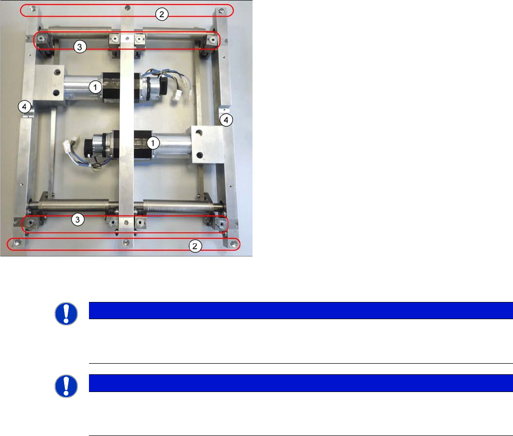
1. Lifting table motors
2. Holes for the fastening screws
3. Four lifting table plate guides
These are part of the lifting mechanism.
4. Fixtures for cable clamps
NOTICE
Single, dual conveyor
The replacement is shown in the diagram using the example of a lifting table unit for the dual
conveyor (DC). Replacement of the lifting table unit for the single conveyor (SC) is the same.
NOTICE
Lifting table up?
If the lifting table stays in the top position, you first need to disconnect the motor from the rods
(see "3.6.2.1.1 Manually Lowering the Lifting Table" [ ➙ 149]).
Service Work Conveyor
3.6.2 Lifting table Conveyor
Service Manual SIPLACE SX1/SX2/DX1/DX2 FS02 149
► Unplug all electrical connections to the lifting table motors (three for each motor).
► Open the cable clamps for the electrical connections.
► Mark the direction of transport for the lifting table. This helps you avoid unintentionally fitting the lifting
table at the wrong angle later on (turned by 180 degrees).
► Loosen the six screws (EC: four screws) fastening the lifting table.
► Carefully lift the lifting table out of the machine.
Installation
► Follow the removal instructions in reverse order for installation. Also observe the following instruc-
tions:
Manually Lowering the Lifting Table
If the lifting table stays in the top position, it can be manually lowered in the event of an emergency.
Procedure
CAUTION
Screws
Make sure that you do not loosen any other screws!
CAUTION
Heavy machine part!
When removing the lifting table, remember it is heavy. You may need to enlist the help of a sec-
ond person.
CAUTION
Installation instructions
► Make sure that the lifting table is aligned correctly in the direction of transport.
► Before you finally fix the lifting table into place, push it up to the stop in the direction of out-
put. This ensures that the lifting table is parallel.
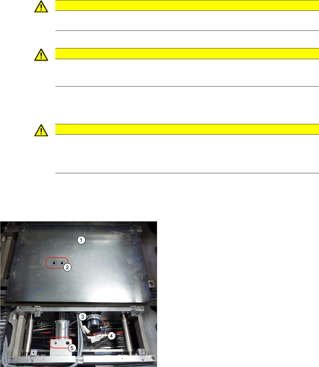
1. Lifting table plate
2. Holes in the lifting table plate
3. Motor.
4. Rods
5. Access to connection screw between rods and motor
► Loosen the screw connecting the rods with the motor,
through the holes in the lifting table plate.
► You can now move the lifting table downwards.
Service Work Conveyor
Conveyor 3.6.2 Lifting table
150 Service Manual SIPLACE SX1/SX2/DX1/DX2 FS02
3.6.2.2
3.6.2.2 Replacing the Lifting Table Motor [03064983-xx]
Replacing the Lifting Table Motor [03064983-xx]
Parts, equipment and tools
▪ BLDC (brushless DC) motor with PLG (planetary gear) and brake [03064983-xx]
Removal
Installation
► Follow the removal instructions in reverse order for installation. Also observe the following instruc-
tions:
See also
4.6.5 Calibrating the Motors in the Conveyor [ ➙ 287]
NOTICE
Lifting table plate guides
► Mark the positions of the lifting table plate guides.
If these are still mistakenly exchanged, you will need to reset the parallelism of the lifting
table plates after installation.
► Remove the lifting table from the machine (see
"3.6.2.1 Replacing the Lifting Table Unit" [ ➙ 148]).
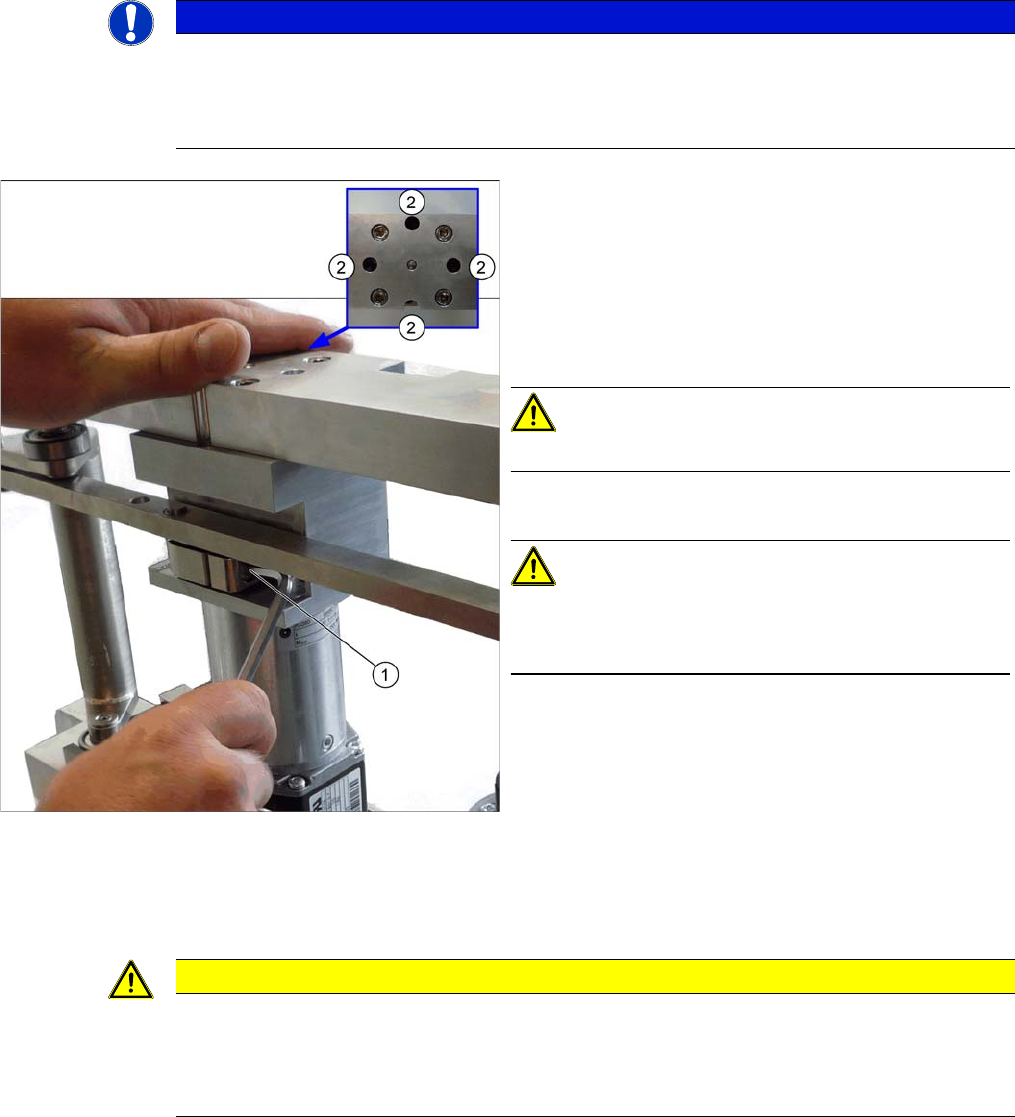
► Unplug the connection between the motor and the
rods (1).
► Loosen the screws (2) fastening the motor. Some of
these are only accessible if you move the rods up-
wards (thereby turning the gear shaft by 90 degrees).
CAUTION!
Make sure that you do not loosen the other four screws!
► Remove the motor.
CAUTION!
There are several shims on the gear shaft. These need to
be taken over to the new motor and fitted there in the
same positions and quantities.
CAUTION
Installation instructions
► Position the washers onto the motor axis in the exact places that they were removed from.
► Make sure that the motor connection cables do not rub against any parts. In particular,
make sure that they do not point upwards or downwards.