00196497-07_SM_SXDX12_en.pdf - 第152页
Service Work Conveyor Conveyor 3.6.3 Conveyor Drive 152 Service Manual SIPLACE SX1/SX2/DX1/DX2 FS02 3.6.3.2 3 . 6 . 3 . 2 R e p la c in g t h e C o n v e y o r D r iv e T o o t h e d B e lt [ 0 3 0 4 7 6 7 7 - x x ] Repl…
Service Work Conveyor
3.6.3 Conveyor Drive Conveyor
Service Manual SIPLACE SX1/SX2/DX1/DX2 FS02 151
3.6.3
3.6.3 Conveyor Drive
Conveyor Drive
3.6.3.1
3.6.3.1 Replacing the Conveyor Drive [03051225-xx]
Replacing the Conveyor Drive [03051225-xx]
Parts, equipment and tools
▪ Conveyor drive [03051225-xx]
▪ Flat spiral spring [03075316-xx] (This is included in the spare parts kit.)
Removal
► Use the software to move the conveyor sides into the position which allows you best access. Alter-
natively, you can also loosen the conveyor side clamps on the dual conveyor (see "3.6.1 Loosening
the Conveyor Side Clamps" [ ➙ 143]).
► Switch off the machine, disconnect it from the power supply and secure it to prevent unauthorized
reactivation. Observe the instructions in section "1.2 Preparatory Work..." [ ➙ 13].
Installation
► Follow the removal instructions in reverse order for installation. Also observe the following instruc-
tions:
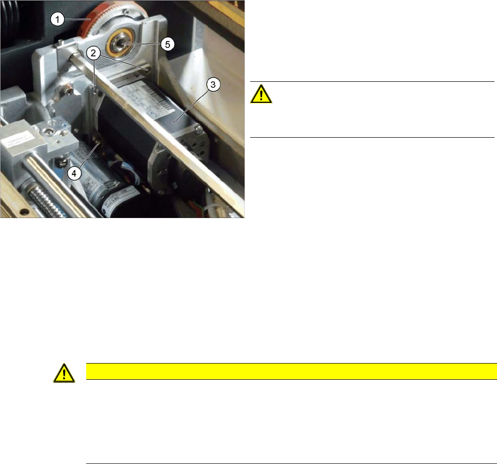
► Loosen the screws fixing the hexagonal shaft above
the conveyor drive and push this carefully into the
machine frame, as has already been done in the
diagram (5). This gives you more room for movement
(see also "3.6.5.3 Replacing the Hexagonal Shaft
[03057258-xx]" [ ➙ 167]).
CAUTION!
There are cables run inside the machine frame.
Make sure you do not damage these cables.
► Unplug the electrical connections to the conveyor
drive (3). Loosen the corresponding cable ties, if re-
quired.
► Fully unscrew the two top screws (2) fastening the
conveyor drive.
► Loosen the lower screw (4) fastening the conveyor
drive but do not full unscrew it.
► Lift the conveyor drive off the bottom screw. While do-
ing so, carefully unthread the conveyor drive from the
toothed belt (1) and remove the conveyor drive from
the machine.
CAUTION
Installation instructions
► Make sure that the toothed belt is positioned accurately in the guidance on the motor shaft
(see diagram below).
► While you tighten the screws fastening the conveyor drive, set the tension of the toothed
belt correctly (see "4.6.1.1 Setting the Tension of the Conveyor Drive Toothed Belt"
[ ➙ 274]).
Service Work Conveyor
Conveyor 3.6.3 Conveyor Drive
152 Service Manual SIPLACE SX1/SX2/DX1/DX2 FS02
3.6.3.2
3.6.3.2 Replacing the Conveyor Drive Toothed Belt [03047677-xx]
Replacing the Conveyor Drive Toothed Belt [03047677-xx]
Parts, equipment and tools
▪ Toothed belt Syncroflex 10 AT3/300 GEN III [03047677-xx]
▪ Flat spiral spring [03075316-xx] (This is included in the spare parts kit.)
Removal
► Dismantle the conveyor drive (see "3.6.3.1 Replacing the Conveyor Drive [03051225-xx]" [ ➙ 151]).
To replace the toothed belt, you do not need to unplug the electrical connections from the conveyor
drive.
Installation
► Follow the removal instructions in reverse order for installation. Also observe the following instruc-
tions:
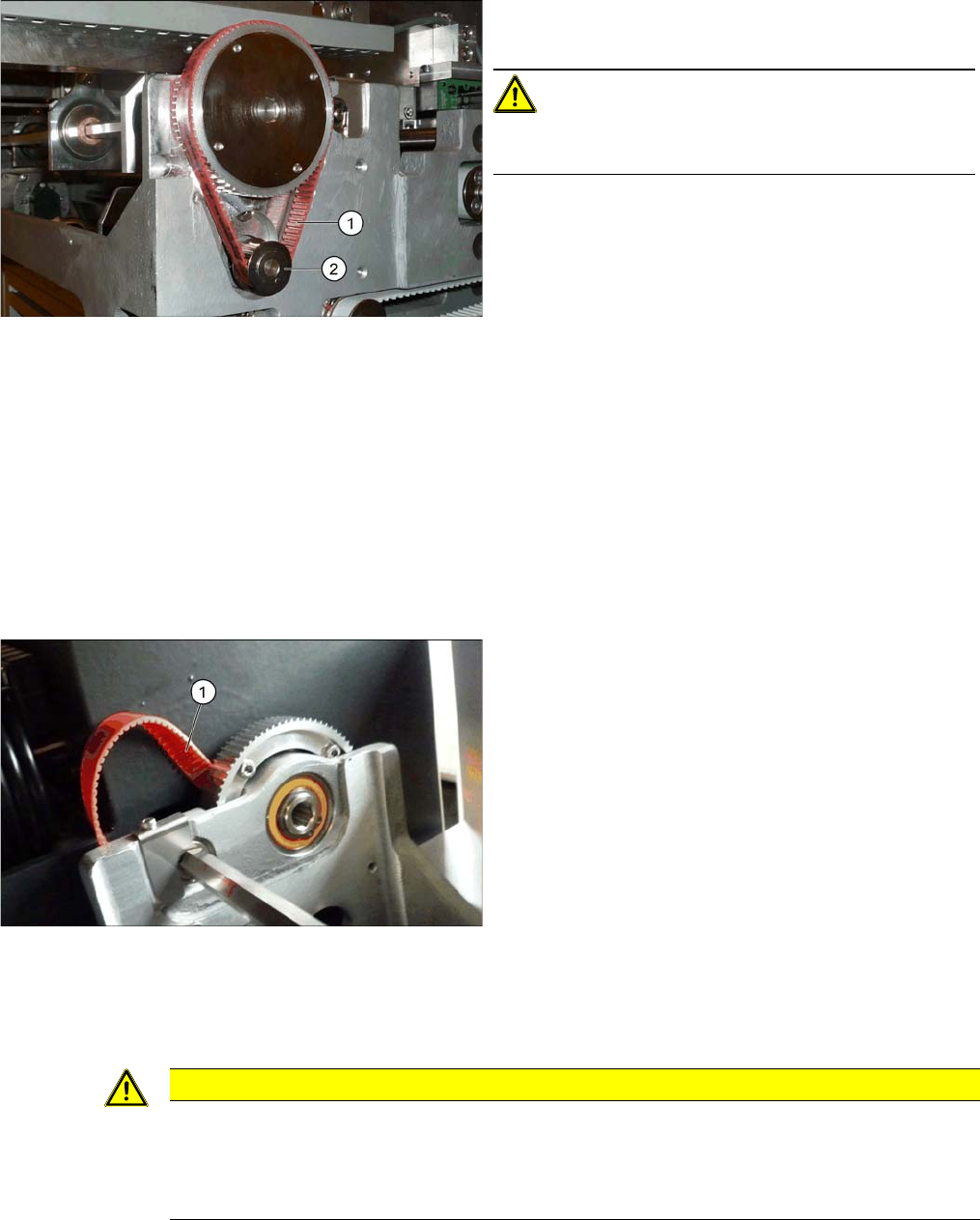
1. Toothed belt for conveyor drive
2. Motor shaft for conveyor drive
CAUTION!
Make sure that the toothed belt is positioned accurately
in the guidance on the motor shaft.
► Pull the conveyor belt (1) carefully out, between the
toothed disk and the machine base.
CAUTION
Installation instructions
► Make sure that the toothed belt is not folded or otherwise damaged.
► While you tighten the screws fastening the motor, set the tension of the toothed belt cor-
rectly (see "4.6.1.1 Setting the Tension of the Conveyor Drive Toothed Belt" [ ➙ 274]).
Service Work Conveyor
3.6.4 Width Adjustment and Adjustment Unit Conveyor
Service Manual SIPLACE SX1/SX2/DX1/DX2 FS02 153
3.6.4
3.6.4 Width Adjustment and Adjustment Unit
Width Adjustment and Adjustment Unit
3.6.4.1
3.6.4.1 Replacing the Cylinder Unit on the Adjustment Unit (Width Adjustment) (DT only)
Replacing the Cylinder Unit on the Adjustment Unit (Width Adjustment) (DT only)
Parts, equipment and tools
There are 2 versions of the cylinder unit, one for the adjustment unit in the input area and one for the
adjustment unit in the output area.
▪ Cylinder unit 1 U2 [03069730-xx]
▪ Cylinder unit 2 U2 [03069731-xx]
Overview
Removal
► Use the software to move the conveyor sides into the position which allows you best access.
► Loosen the clamps on the conveyor sides (see "3.6.1 Loosening the Conveyor Side Clamps"
[ ➙ 143]).
► Switch off the machine, disconnect it from the power supply and secure it to prevent unauthorized
reactivation. Observe the instructions in section "1.2 Preparatory Work..." [ ➙ 13].
► Loosen the screws fastening the right-hand lifting table plate (viewed in the direction of transport)
and remove this lifting table plate.
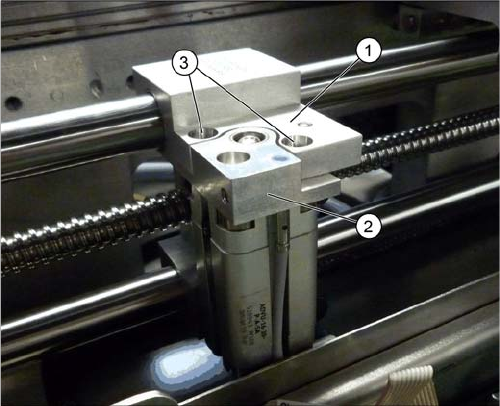
1. Adjustment unit
2. Cylinder unit
3. Screw fastening the cylinder unit