00196497-07_SM_SXDX12_en.pdf - 第158页
Service Work Conveyor Conveyor 3.6. 4 Width Adjustment and Adjustment Unit 158 Service Manual SIPLACE SX1/SX2/DX1/DX2 FS02 Installation ► Follow the removal in structions in reverse order for installati o n. Also observe…
Service Work Conveyor
3.6.4 Width Adjustment and Adjustment Unit Conveyor
Service Manual SIPLACE SX1/SX2/DX1/DX2 FS02 157
3.6.4.4
3.6.4.4 Replacing the Width Adjustment Deflection Pulley [00337887-xx]
Replacing the Width Adjustment Deflection Pulley [00337887-xx]
Parts, equipment and tools
▪ Deflection pulley assembly for width adjustment [00337887-xx]
Overview
Removal
► Use the software to move the conveyor sides into the position which allows you best access. Alter-
natively, you can also loosen the conveyor trolley clamps (see "3.6.1 Loosening the Conveyor Side
Clamps" [ ➙ 143]).
► Switch off the machine and secure it to prevent unauthorized reactivation. Observe the instructions
in section "1.2 Preparatory Work..." [ ➙ 13].
► Loosen the screws fastening the width adjustment drive unit. This toothed belt is now loose.
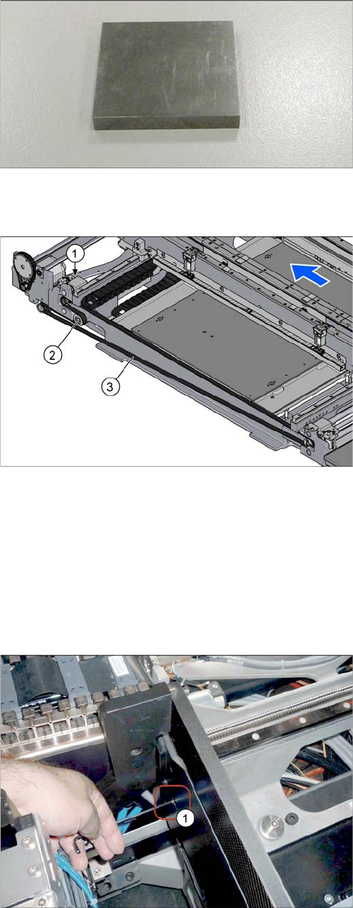
▪ To check the adjustment unit stoppers, you need two
suitably sized and identical pieces of metal (see be-
low).
You could also use two lifting table plate guides if
needed.
1. Drive unit of width adjustment
2. Deflection pulley for width adjustment
3. Toothed belt of width adjustment
► Loosen the fastening screw on the deflection pulley
and take the deflection pulley out of the machine.
The screw fastening the deflection pulley can be
reached via a hole (1) in the machine base.
You might have to push the COT insert outwards (see
"3.10.2 Replacing the SX1/SX2 Component Trolley
Feed Device Assembly [03059353-xx]" [ ➙ 207]).
Service Work Conveyor
Conveyor 3.6.4 Width Adjustment and Adjustment Unit
158 Service Manual SIPLACE SX1/SX2/DX1/DX2 FS02
Installation
► Follow the removal instructions in reverse order for installation. Also observe the following instruc-
tions:
3.6.4.5
3.6.4.5 Replacing the Drive Unit (Width Adjustment) [03048184-xx]
Replacing the Drive Unit (Width Adjustment) [03048184-xx]
Parts, equipment and tools
▪ Drive unit for width adjustment [03048184-xx]
Overview
CAUTION
Installation instructions
► Carefully thread in the toothed belt. To do this, carefully lift the toothed belt a little ( e.g. with
the shorter end of an Allen key).
► Hand-tighten the screw fastening the deflection pulley.
► Make sure that the adjustment units run exactly parallel to one another. (see "4.6.4 Setting
the Parallelism of the Conveyor Sides" [ ➙ 283]).
► Set the belt tension to 20 +/- 2 Hz (see "4.6.1.3 Setting the Tension of the Width Adjustment
Toothed Belt" [ ➙ 276]).
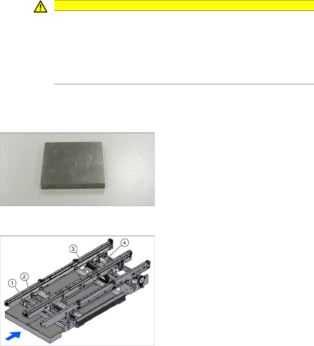
▪ To check the adjustment unit stoppers, you need two
suitably sized and identical pieces of metal (see be-
low).
You could also use two lifting table plate guides if
needed.
Width adjustment for dual conveyor
1. Adjustment unit
2. Recirculating spindle
3. Toothed belt of width adjustment
4. Drive unit (stepping motor) of width adjustment
Service Work Conveyor
3.6.4 Width Adjustment and Adjustment Unit Conveyor
Service Manual SIPLACE SX1/SX2/DX1/DX2 FS02 159
Removal
► Use the software to move the conveyor sides into the position which allows you best access. Alter-
natively, you can also loosen the conveyor side clamps on the dual conveyor (see "3.6.1 Loosening
the Conveyor Side Clamps" [ ➙ 143]).
► Switch off the machine, disconnect it from the power supply and secure it to prevent unauthorized
reactivation. Observe the instructions in section "1.2 Preparatory Work..." [ ➙ 13].
Installation
► Follow the removal instructions in reverse order for installation. Also observe the following instruc-
tions:
See also
4.6.1.1 Setting the Tension of the Conveyor Drive Toothed Belt [ ➙ 274]
4.6.5 Calibrating the Motors in the Conveyor [ ➙ 287]
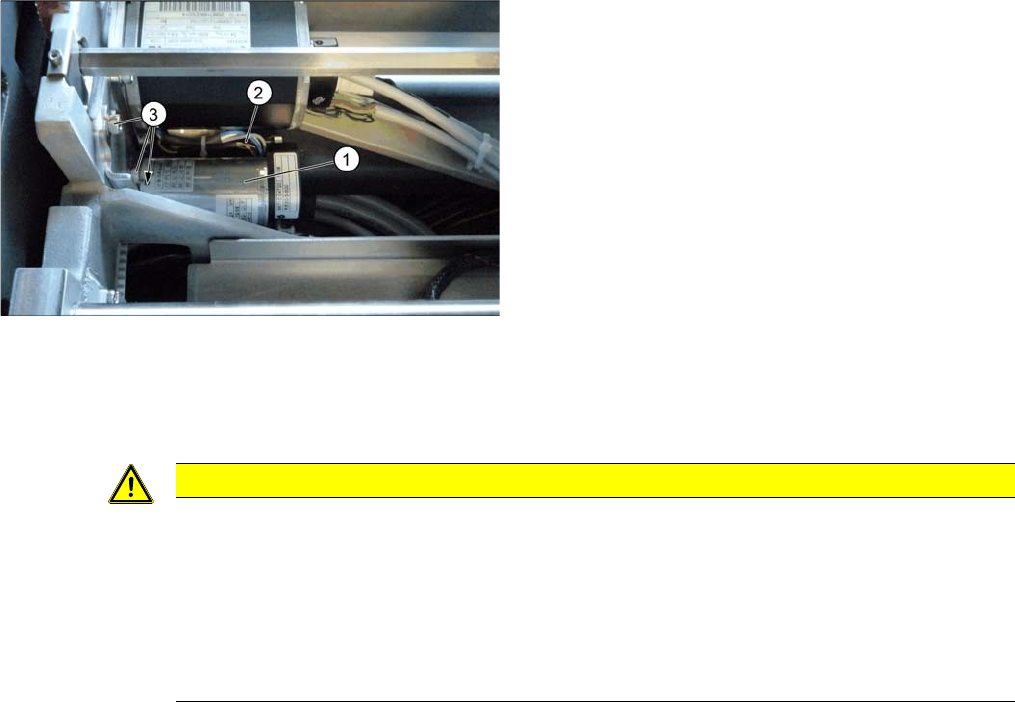
► Loosen the three screws (3) fastening the drive
unit (1).
► Pull out the drive unit. To do this, carefully unthread
the drive unit from the toothed belt.
► Unplug the electrical connections (2) to the drive unit
and then remove the drive unit from the machine.
CAUTION
Installation instructions
► Carefully thread in the toothed belt. To do this, carefully lift the toothed belt a little ( e.g. with
the shorter end of an Allen key).
► Make sure that the adjustment units run exactly parallel to one another. (see "4.6.4 Setting
the Parallelism of the Conveyor Sides" [ ➙ 283]).
► Set the belt tension to 20 +/- 2 Hz (see "4.6.1.3 Setting the Tension of the Width Adjustment
Toothed Belt" [ ➙ 276]).