00196497-07_SM_SXDX12_en.pdf - 第160页
Service Work Conveyor Conveyor 3.6. 4 Width Adjustment and Adjustment Unit 160 Service Manual SIPLACE SX1/SX2/DX1/DX2 FS02 3.6.4.6 3 . 6 . 4 . 6 R e p la c in g t h e C la m p in g U n it ( W id t h A d ju s t m e n t ) …
Service Work Conveyor
3.6.4 Width Adjustment and Adjustment Unit Conveyor
Service Manual SIPLACE SX1/SX2/DX1/DX2 FS02 159
Removal
► Use the software to move the conveyor sides into the position which allows you best access. Alter-
natively, you can also loosen the conveyor side clamps on the dual conveyor (see "3.6.1 Loosening
the Conveyor Side Clamps" [ ➙ 143]).
► Switch off the machine, disconnect it from the power supply and secure it to prevent unauthorized
reactivation. Observe the instructions in section "1.2 Preparatory Work..." [ ➙ 13].
Installation
► Follow the removal instructions in reverse order for installation. Also observe the following instruc-
tions:
See also
4.6.1.1 Setting the Tension of the Conveyor Drive Toothed Belt [ ➙ 274]
4.6.5 Calibrating the Motors in the Conveyor [ ➙ 287]
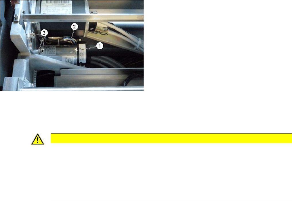
► Loosen the three screws (3) fastening the drive
unit (1).
► Pull out the drive unit. To do this, carefully unthread
the drive unit from the toothed belt.
► Unplug the electrical connections (2) to the drive unit
and then remove the drive unit from the machine.
CAUTION
Installation instructions
► Carefully thread in the toothed belt. To do this, carefully lift the toothed belt a little ( e.g. with
the shorter end of an Allen key).
► Make sure that the adjustment units run exactly parallel to one another. (see "4.6.4 Setting
the Parallelism of the Conveyor Sides" [ ➙ 283]).
► Set the belt tension to 20 +/- 2 Hz (see "4.6.1.3 Setting the Tension of the Width Adjustment
Toothed Belt" [ ➙ 276]).
Service Work Conveyor
Conveyor 3.6.4 Width Adjustment and Adjustment Unit
160 Service Manual SIPLACE SX1/SX2/DX1/DX2 FS02
3.6.4.6
3.6.4.6 Replacing the Clamping Unit (Width Adjustment)
Replacing the Clamping Unit (Width Adjustment)
Parts, equipment and tools
There are two variants of the clamping units. These are not compatible with one another. Select the ap-
plicable one:
▪Variant 1:
Clamping unit 1 [03051029-xx] or
Clamping unit 2 [03051192-xx]
▪Variant 2:
Clamping unit SX4 1.1 [03084719-xx]
Clamping unit SX4 2.1 [03084754-xx]
Removal
► Switch off the machine and secure it to prevent unauthorized reactivation. Observe the instructions
in section "1.2 Preparatory Work..." [ ➙ 13].
► Loosen the clamps on the conveyor sides. In particular, loosen the clamp to be replaced (see "3.6.1
Loosening the Conveyor Side Clamps" [ ➙ 143]).
Installation
► Follow the removal instructions in reverse order for installation. Also observe the following instruc-
tions:
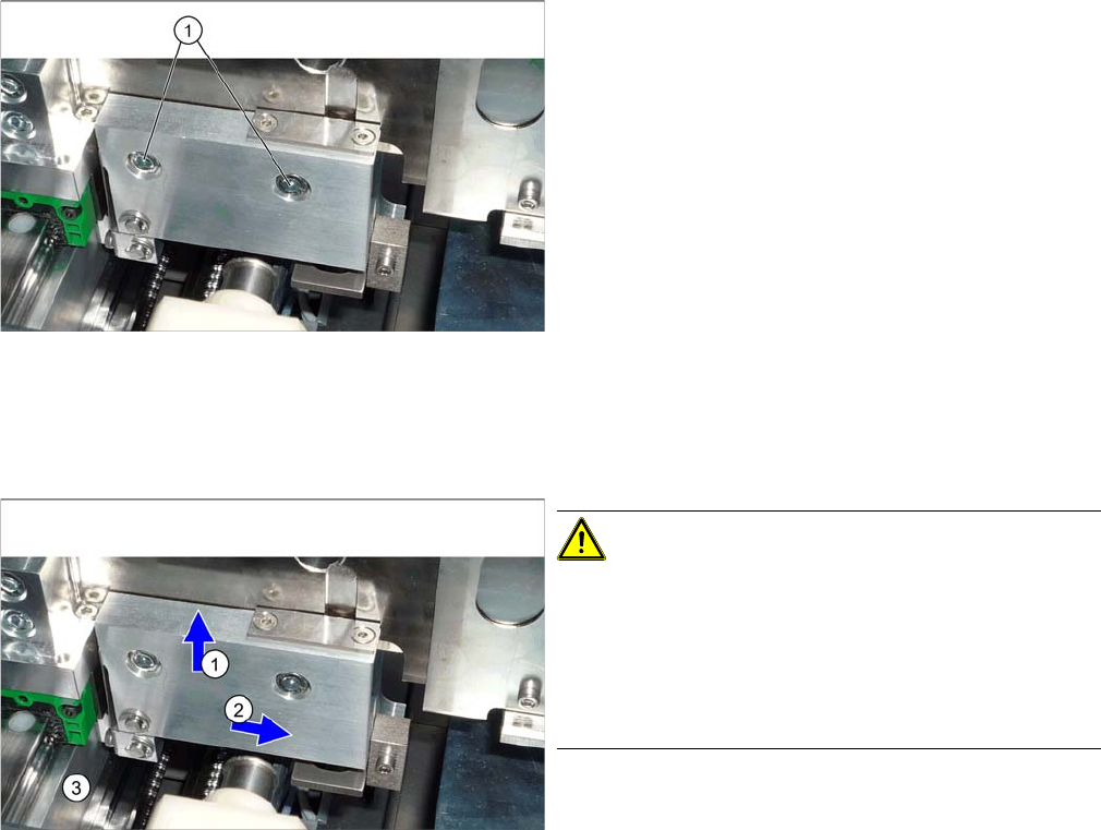
► Loosen the two screws fastening the clamps and re-
move the clamps.
CAUTION!
Installation instructions
During assembly, press the clamp upwards (1) and
sideways (2), away from the clamping surface (3).
Check the distance between the clamp and the adjust-
ment unit. There must be room for a 0.4 mm feeler
gauge.
Service Work Conveyor
3.6.4 Width Adjustment and Adjustment Unit Conveyor
Service Manual SIPLACE SX1/SX2/DX1/DX2 FS02 161
3.6.4.7
3.6.4.7 Replacing the Pressure Spring in the Clamping Unit (Width Adjustment) [00359374-xx] (DC Only)
Replacing the Pressure Spring in the Clamping Unit (Width Adjustment) [00359374-xx] (DC
Only)
Parts, equipment and tools
▪ Compression spring 1.25*7.55*51.5 V2A [00359374-xx]
Removal
Installation
► Follow the removal instructions in reverse order for installation.
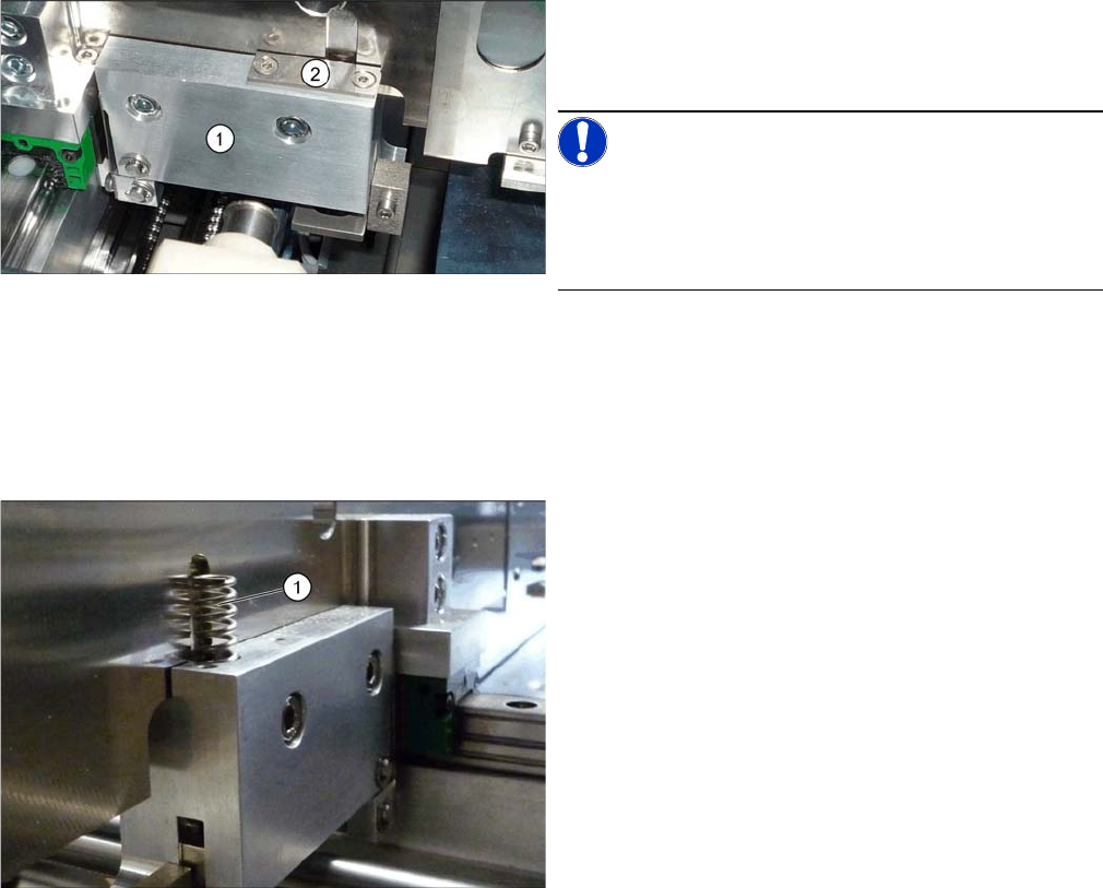
1. Clamping unit version 1
2. Disk above the pressure spring
NOTICE!
Replacement of the pressure spring is only possible for
version 1 clamping units (see diagram). In the case of all
other versions, the complete clamping unit must be re-
placed for service work.
► To remove the compression spring, you need to loos-
en the respective clamps. (see "3.6.1 Loosening the
Conveyor Side Clamps" [ ➙ 143]).
► Remove the spring (1) from the clamp.