00196497-07_SM_SXDX12_en.pdf - 第170页
Service Work Conveyor Conveyor 3.6.6 Clamping plate 170 Service Manual SIPLACE SX1/SX2/DX1/DX2 FS02 3.6.6 3 . 6 . 6 C la m p in g p la t e Clamping plate 3.6.6.1 3 . 6 . 6 . 1 R e p la c in g t h e C la m p in g P la t e…
Service Work Conveyor
3.6.5 Conveyor Belt, Belt Drive and Hexagonal Shaft Conveyor
Service Manual SIPLACE SX1/SX2/DX1/DX2 FS02 169
Removal
► Use the software to move the conveyor sides into the position which allows you best access. Alter-
natively, you can also loosen the conveyor side clamps on the dual conveyor (see "3.6.1 Loosening
the Conveyor Side Clamps" [ ➙ 143]).
► Switch off the machine, disconnect it from the power supply and secure it to prevent unauthorized
reactivation. Observe the instructions in section "1.2 Preparatory Work..." [ ➙ 13].
► Dismantle the clamping plate (see "3.6.6.1 Replacing the Clamping Plate" [ ➙ 170]).
► Loosen the screws fastening the three guide rails and then remove them.
► If there are also stoppers on the side, dismantle these (see "3.6.7.1 Replacing the Stopper (Stopper
on the Conveyor Side) [03081405-xx] (FS01)" [ ➙ 174]).
Mark their position, to make clear assignment easier later on.
► Loosen the idler.
► Depending on the lane for which the toothed belt needs to be replaced, you may need to move the
relevant hexagonal shaft so that the toothed belt can be unthreaded. To do this, loosen the screw
fastening the respective hexagonal shaft and move the shaft within the opening in the machine
frame.
► Remove the toothed belt from the machine.
Installation
► Follow the removal instructions in reverse order for installation. Also observe the following instruc-
tions:
See also
4.6.1.2 Setting the Tension of the Conveyor Toothed Belt [ ➙ 275]
CAUTION
Toothed belt
► Make sure that the toothed belt is not folded!
CAUTION
Cable
There are cables run inside the machine frame.
► Make sure you do not damage these cables.
CAUTION
Installation instructions
► Make sure that the toothed belt is not folded or otherwise damaged!
► Pretension the toothed belt slightly, otherwise it might get caught when you fit the guide rails
and the clamping plate.
Service Work Conveyor
Conveyor 3.6.6 Clamping plate
170 Service Manual SIPLACE SX1/SX2/DX1/DX2 FS02
3.6.6
3.6.6 Clamping plate
Clamping plate
3.6.6.1
3.6.6.1 Replacing the Clamping Plate
Replacing the Clamping Plate
Parts, equipment and tools
▪ FS01: clamping plate assembly [03055141-xx]
▪ FS02: clamping plate assembly [03084918-xx]
Overview
Removal
► Use the software to move the conveyor sides into the position which allows you best access. Alter-
natively, you can also loosen the conveyor side clamps on the dual conveyor (see "3.6.1 Loosening
the Conveyor Side Clamps" [ ➙ 143]).
► Switch off the machine, disconnect it from the power supply and secure it to prevent unauthorized
reactivation. Observe the instructions in section "1.2 Preparatory Work..." [ ➙ 13].
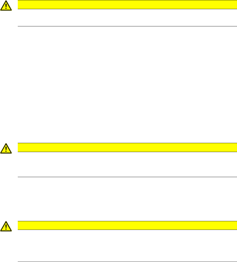
► Loosen the six screws fastening the clamping plate and remove the clamping plate.
NOTICE
Differences
► The clamping plates are not compatible.
► Removal and installation are explained in the following section, using the example of the
clamping plate for FS01. Removal and installation for the FS02 follows the same procedure.
1. Fastening screws (6x) for clamping plate
2. Clamping plate
1. Clamping plate assembly [03055141-xx] for FS01
with two plastic clamping plate guides [03066634-xx]
2. Clamping plate assembly [03084918-xx] for FS02
with four brass clamping plate guides [03084490-xx]
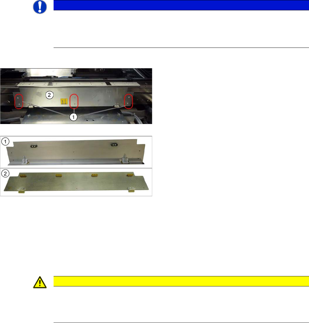
CAUTION
Compression springs
There are two pressure springs down on the clamping plate [00364715-xx]. These are pressur-
ized when fitted.
► Make sure that you do not lose the pressure springs.
Service Work Conveyor
3.6.6 Clamping plate Conveyor
Service Manual SIPLACE SX1/SX2/DX1/DX2 FS02 171
Installation
► Follow the removal instructions in reverse order for installation. Also observe the following instruc-
tions:
3.6.6.2
3.6.6.2 Replacing the Compression Spring on the Clamping Plate [00364715-xx]
Replacing the Compression Spring on the Clamping Plate [00364715-xx]
Parts, equipment and tools
▪ Compression spring 0.63*5.63*26 [00364715-xx]
Removal
► Dismantle the clamping plate (see "3.6.6.1 Replacing the Clamping Plate" [ ➙ 170]).
► Remove the compression spring.
Installation
► Follow the removal instructions in reverse order for installation.
See also
3.6.1 Loosening the Conveyor Side Clamps [ ➙ 143]
3.6.6.3
3.6.6.3 Replacing the Sliding Strips and Sliding Carriage
Replacing the Sliding Strips and Sliding Carriage
Parts, equipment and tools
▪FS01:
Sliding strips [03052960-xx]
Sliding carriage [03052961-xx]
▪FS02:
Sliding strips [03084492-xx]
Sliding carriage [03084491-xx]
▪ Loctite 241 [02101037-xx]
CAUTION!
Installation instructions
Reinsert the compression springs (1).
Check the clamping plate for ease of movement.
NOTICE
FS01 and FS02
The pressure springs are identical for conveyors with FS01 and those with FS02.
NOTICE
Replace together
We recommend that you always replace the sliding strips and sliding carriage together.
There are six sliding strips and three sliding carriages fitted for each clamping plate.
It is also advisable to replace the clamping plate guides at the same time (see "3.6.6.4 Replac-
ing the Clamping Plate Guides " [ ➙ 173]).