00196497-07_SM_SXDX12_en.pdf - 第175页
Service Work Conveyor 3.6.7 Stoppers and Sensors Conveyor Service Manual SIPLACE SX1/SX2/DX1/DX2 FS02 175 Installation The following steps must be perfo rmed when fitting a stopper with sensor : The following steps are e…
Service Work Conveyor
Conveyor 3.6.7 Stoppers and Sensors
174 Service Manual SIPLACE SX1/SX2/DX1/DX2 FS02
3.6.7
3.6.7 Stoppers and Sensors
Stoppers and Sensors
3.6.7.1
3.6.7.1 Replacing the Stopper (Stopper on the Conveyor Side) [03081405-xx] (FS01)
Replacing the Stopper (Stopper on the Conveyor Side) [03081405-xx] (FS01)
Parts, equipment and tools
▪ Stopper [03081405-xx] (without sensor)
Overview
Removal
► Use the software to move the conveyor sides into the position which allows you best access. Alter-
natively, you can also loosen the conveyor side clamps on the dual conveyor (see "3.6.1 Loosening
the Conveyor Side Clamps" [ ➙ 143]).
► Switch off the machine, disconnect it from the power supply and secure it to prevent unauthorized
reactivation. Observe the instructions in section "1.2 Preparatory Work..." [ ➙ 13].
► Unplug the electrical connections from the stopper
► Loosen the two screws fastening the stopper and remove the stopper.
CAUTION
Replacing an old stopper with sensor [03059129-xx]
If an old stopper with sensor is replaced with a new stopper without sensor, you need to observe
the following points:
► The station software must have at least version 703.02 HF4.
► The DIP switch on the conveyor control must be set so that the sensors at all stoppers are
no longer queried.
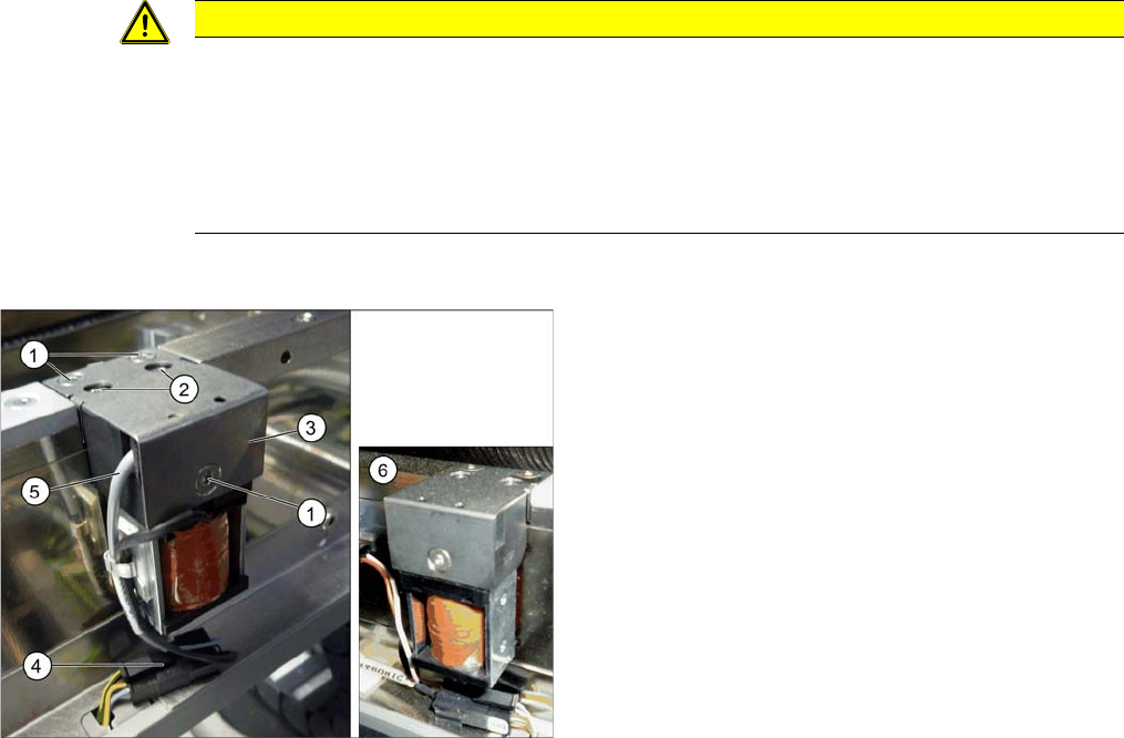
Side stopper with [03059129-xx] and without [03081405-
xx] sensor
1. Screws for fastening the cover plate
2. Screws for fastening the stopper
3. Cover plate
4. Electrical connections
5. Sensor cable (moved out of the stopper here, on the
left)
6. Side stopper without sensor
Service Work Conveyor
3.6.7 Stoppers and Sensors Conveyor
Service Manual SIPLACE SX1/SX2/DX1/DX2 FS02 175
Installation
The following steps must be performed when fitting a stopper with sensor:
The following steps are essential for stoppers with sensor, irrespective of any conversions which may
be performed:
► Fix the cable clamp to the relevant side of the stopper, thereby fastening the cable.
The following steps must be performed for stoppers with and without sensor:
► Follow the removal instructions in reverse order for further installation. Also observe the following
instructions:
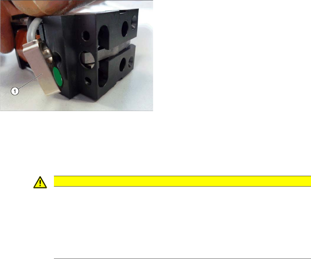
The stopper may need to be prepared for installation. De-
pending on the installation position, the cable will need to
be fixed to the left or right side of the stopper.
► Compare the new stopper with the old one. If the sen-
sor cable for the new stopper is on the wrong side,
you will need to change this. Proceed as follows:
⇨ Loosen the screws fastening the cover plate.
⇨ Turn the sensor (1) to the correct side. The cable
should now be on the correct side of the stopper.
⇨ Fasten the cover plate again with the correspond-
ing screws.
CAUTION
Installation instructions
► Make sure that the cable is run correctly and does not rub against any parts.
► Tighten the screws fastening the stopper with care, otherwise the plastic housing of the
stopper could be damaged.
► Only use the socket head screws (Allen screws) in the placement area. If you use the hex-
agon head screws from the input/output area, this could cause a crash!
► Check the DIP switch setting for the stopper at the conveyor control (see "5.3.1 TSP400
[03057341-xx]" [ ➙ 321] and "5.3.2 TSP400E [03057342-xx]" [ ➙ 325]).
Service Work Conveyor
Conveyor 3.6.7 Stoppers and Sensors
176 Service Manual SIPLACE SX1/SX2/DX1/DX2 FS02
3.6.7.2
3.6.7.2 Replacing the Stopper (Sensor Rail) [03084034-xx] (FS02)
Replacing the Stopper (Sensor Rail) [03084034-xx] (FS02)
Parts, equipment and tools
▪ Stopper 25 SX pneumatic assembly [03084034-xx]
Overview
Removal
► Use the software to move the conveyor sides into the position which allows you best access. Alter-
natively, you can also loosen the conveyor side clamps on the dual conveyor (see "3.6.1 Loosening
the Conveyor Side Clamps" [ ➙ 143]).
Installation
► Follow the removal instructions in reverse order for installation. Also observe the following instruc-
tions:
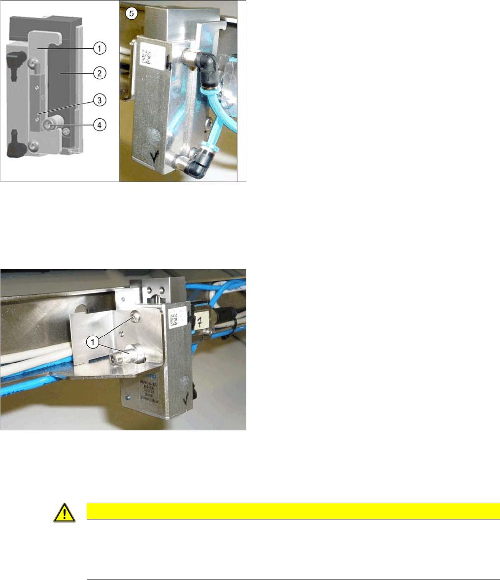
Basic stopper unit
1. Stroke limitation rail
2. Stop rail
3. Sensor for bottom end position stopper
[03066803-xx]
There are several variants of this stopper, with and
without (5) this sensor.
4. Stopper bolt
5. Stopper without "sensor for bottom end position stop-
per"
► Switch off the machine, disconnect it from the power
supply and secure it to prevent unauthorized reacti-
vation. Observe the instructions in section "1.2 Pre-
paratory Work..." [ ➙ 13].
► Loosen all electrical and pneumatic connections to
the stopper. You may want to mark their positions, to
make clear assignment easier later on.
► Loosen the two screws (1) fastening the stopper and
remove the stopper.
CAUTION
Installation instructions
► Make sure that the cable is run correctly and does not rub against any parts.
► Check the DIP switch setting for the stopper at the conveyor control (see "5.3.1 TSP400
[03057341-xx]" [ ➙ 321]).