00196497-07_SM_SXDX12_en.pdf - 第176页
Service Work Conveyor Conveyor 3.6.7 Stoppers and Sensors 176 Service Manual SIPLACE SX1/SX2/DX1/DX2 FS02 3.6.7.2 3 . 6 . 7 . 2 R e p la c in g t h e S t o p p e r ( S e n s o r R a il) [ 0 3 0 8 4 0 3 4 - x x ] ( F S 0 …
Service Work Conveyor
3.6.7 Stoppers and Sensors Conveyor
Service Manual SIPLACE SX1/SX2/DX1/DX2 FS02 175
Installation
The following steps must be performed when fitting a stopper with sensor:
The following steps are essential for stoppers with sensor, irrespective of any conversions which may
be performed:
► Fix the cable clamp to the relevant side of the stopper, thereby fastening the cable.
The following steps must be performed for stoppers with and without sensor:
► Follow the removal instructions in reverse order for further installation. Also observe the following
instructions:
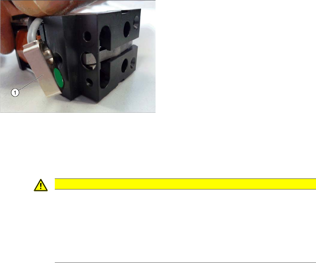
The stopper may need to be prepared for installation. De-
pending on the installation position, the cable will need to
be fixed to the left or right side of the stopper.
► Compare the new stopper with the old one. If the sen-
sor cable for the new stopper is on the wrong side,
you will need to change this. Proceed as follows:
⇨ Loosen the screws fastening the cover plate.
⇨ Turn the sensor (1) to the correct side. The cable
should now be on the correct side of the stopper.
⇨ Fasten the cover plate again with the correspond-
ing screws.
CAUTION
Installation instructions
► Make sure that the cable is run correctly and does not rub against any parts.
► Tighten the screws fastening the stopper with care, otherwise the plastic housing of the
stopper could be damaged.
► Only use the socket head screws (Allen screws) in the placement area. If you use the hex-
agon head screws from the input/output area, this could cause a crash!
► Check the DIP switch setting for the stopper at the conveyor control (see "5.3.1 TSP400
[03057341-xx]" [ ➙ 321] and "5.3.2 TSP400E [03057342-xx]" [ ➙ 325]).
Service Work Conveyor
Conveyor 3.6.7 Stoppers and Sensors
176 Service Manual SIPLACE SX1/SX2/DX1/DX2 FS02
3.6.7.2
3.6.7.2 Replacing the Stopper (Sensor Rail) [03084034-xx] (FS02)
Replacing the Stopper (Sensor Rail) [03084034-xx] (FS02)
Parts, equipment and tools
▪ Stopper 25 SX pneumatic assembly [03084034-xx]
Overview
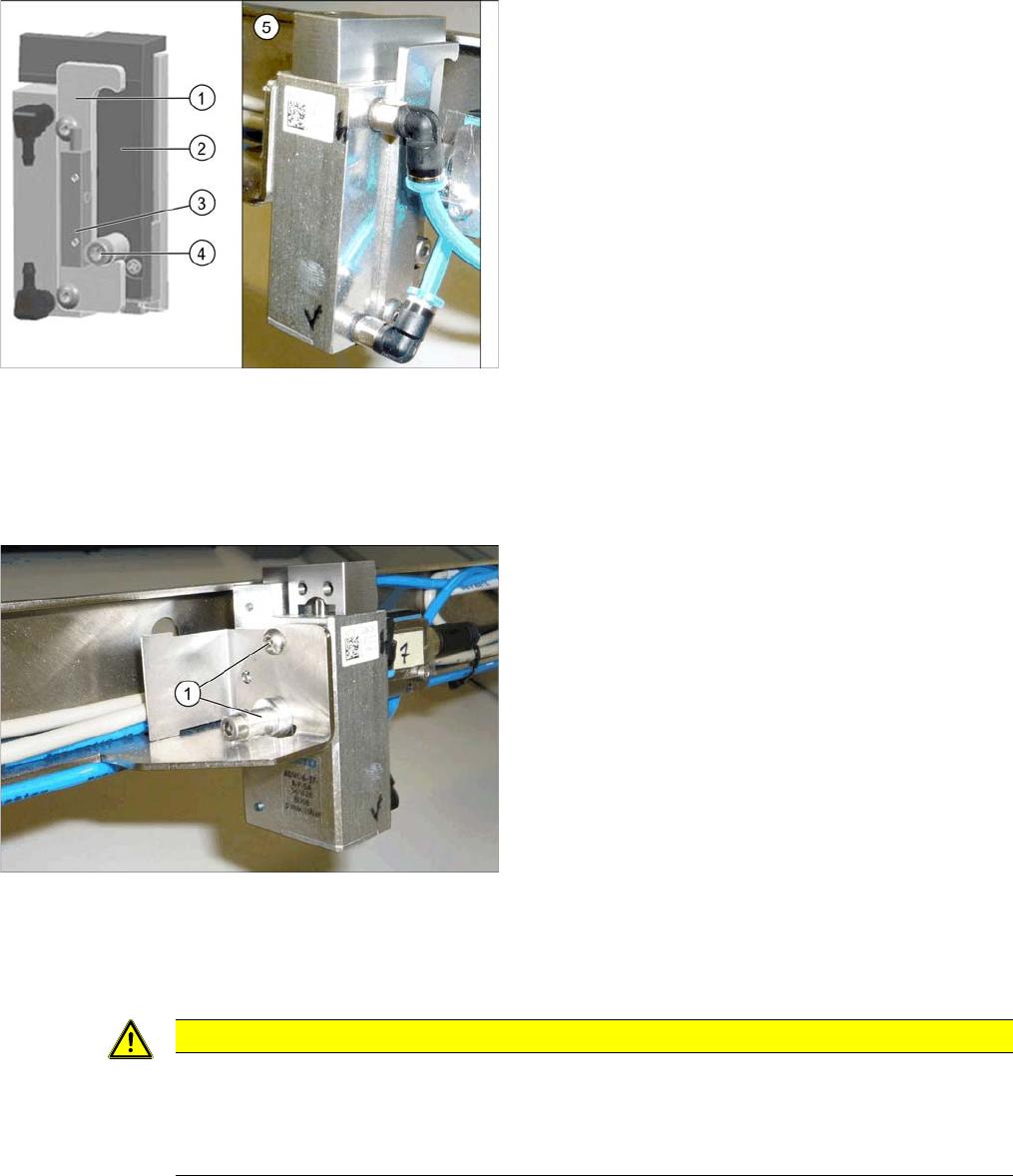
Removal
► Use the software to move the conveyor sides into the position which allows you best access. Alter-
natively, you can also loosen the conveyor side clamps on the dual conveyor (see "3.6.1 Loosening
the Conveyor Side Clamps" [ ➙ 143]).
Installation
► Follow the removal instructions in reverse order for installation. Also observe the following instruc-
tions:
Basic stopper unit
1. Stroke limitation rail
2. Stop rail
3. Sensor for bottom end position stopper
[03066803-xx]
There are several variants of this stopper, with and
without (5) this sensor.
4. Stopper bolt
5. Stopper without "sensor for bottom end position stop-
per"
► Switch off the machine, disconnect it from the power
supply and secure it to prevent unauthorized reacti-
vation. Observe the instructions in section "1.2 Pre-
paratory Work..." [ ➙ 13].
► Loosen all electrical and pneumatic connections to
the stopper. You may want to mark their positions, to
make clear assignment easier later on.
► Loosen the two screws (1) fastening the stopper and
remove the stopper.
CAUTION
Installation instructions
► Make sure that the cable is run correctly and does not rub against any parts.
► Check the DIP switch setting for the stopper at the conveyor control (see "5.3.1 TSP400
[03057341-xx]" [ ➙ 321]).
Service Work Conveyor
3.6.7 Stoppers and Sensors Conveyor
Service Manual SIPLACE SX1/SX2/DX1/DX2 FS02 177
3.6.7.3
3.6.7.3 Replacing the Sonar Sensor PXS240 [03089004Sxx]
Replacing the Sonar Sensor PXS240 [03089004Sxx]
All sonar sensors used can be disconnected for replacement and dismantled.
Parts, equipment and tools
▪ Programming cable for PXS240 sensor [03073330-xx]
▪ Sonar sensor UB100-F77 [03089004Sxx] (compatible)
Incl. 2x "Press-in thread insert M2" [03088352-xx]
(replaces: old: sonar sensor PXS240 [03069863-xx])
▪ Setting gauge for ultrasonic sensors [03076989-xx]
▪ Loctite 401 [00805104-xx], if required
Overview
Removal
► Use the software to move the conveyor sides into the position which allows you best access. Alter-
natively, you can also loosen the conveyor side clamps on the dual conveyor (see "3.6.1 Loosening
the Conveyor Side Clamps" [ ➙ 143]).
► Switch off the machine, disconnect it from the power supply and secure it to prevent unauthorized
reactivation. Observe the instructions in section "1.2 Preparatory Work..." [ ➙ 13].
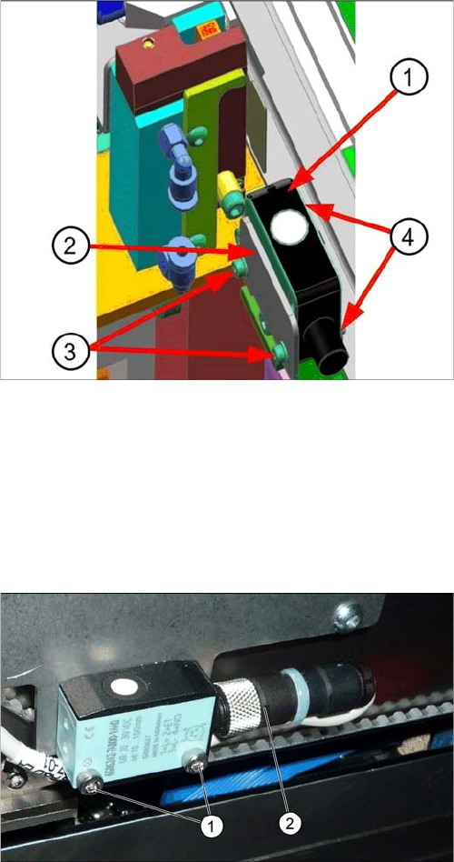
Sonar sensor on the stopper positions:
1. Sonar sensor
2. Sensor rail fixture bracket
3. Fastening screws ISO4762–M2x16-A2-70
[03042529-xx] with washers DIN125-A2.2-140HV-A2
[00301541-xx].
4. Press-in nuts
► Dismantle any cover which is on the sonar sensor.
► Loosen the screws (1) fastening the ultrasonic sen-
sors.
► Unscrew the press-fit connection (2) from the ultra-
sonic sensor and remove the ultrasonic sensor from
the machine.